Injection Molding Vision Inspection: How to Design Reliable Mold Protection and Part Quality Checks
2026-09-03 15:18:26
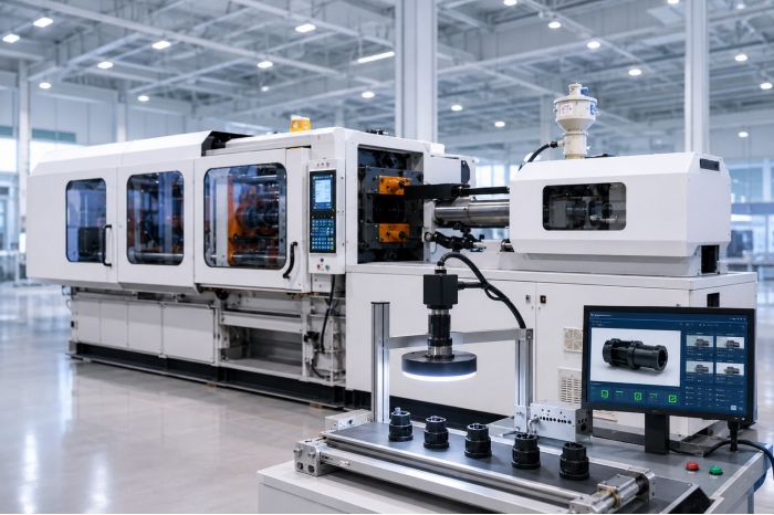
Machine vision is increasingly used in injection molding to inspect mold conditions, verify part removal, check inserted components, detect product defects, and support automated quality control. However, successful injection molding vision inspection requires more than installing an industrial camera and defining an OK or NG image.
The inspection must take place at the correct point in the molding cycle. The target must be visible under controlled optical conditions. The system must have enough time to capture and process the image, and the injection molding machine must know how to respond when the result is OK, NG, or uncertain.
For this reason, machine vision should be treated as part of the production process rather than as an independent inspection device.
A practical engineering evaluation can begin with four questions:
- Can the system see the target clearly?
- Can it judge the condition correctly?
- Can it complete the judgment within the available time?
- Can the production equipment respond correctly when an abnormal condition is detected?
These questions are more useful than starting with camera resolution alone.
A vision system converts images into information, but that information becomes useful only when it connects to the molding process.

Consider a molded part that remains inside the cavity after ejection. If the part is detected later at an offline inspection station, the product may be identified as abnormal, but the mold has not been protected. To protect the mold, inspection must occur before the next mold closing action is permitted.
Product quality inspection has a different requirement.
A short shot, flash, black spot, scratch, dimensional feature, color variation, barcode, or character usually needs inspection after the part has reached a stable position for imaging. Depending on the application, the part may be placed in a fixture, transferred by a robot, or presented to several cameras before a reliable decision can be made.
These two tasks therefore serve different purposes.
In HUARONG's system architecture, the HCM Series is used for in-mold safety monitoring before the next molding cycle, while the HCP Series is used for product quality inspection after part removal or at a dedicated inspection position.
Further reading: Common Injection Molding Defects: Causes, Types, and Solutions
Before selecting cameras, lenses, or software, the project should first define what decision the vision system needs to make.
| Engineering Question | HCM Series | HCP Series |
|---|---|---|
| Main decision | Is the mold area ready for the next machine action? | Does the part meet the defined quality criteria? |
| Typical inspection stage | After mold opening and before the next mold closing | After part removal or at an inspection station |
| Typical targets | Residual parts, inserts, ejection status, part removal, cavity status | Short shots, flash, surface defects, dimensions, color, codes |
| Main NG response | Stop or block the next machine action | Reject, separate, record, or review the product |
| Main integration | Injection molding machine, robot, PLC, I/O | Fixture, robot, conveyor, PLC, traceability system |
This is a process planning framework rather than a fixed machine specification.

The HCM Series is designed around a specific control window: after the mold has opened and before the next potentially hazardous motion is allowed.
Depending on the application, the system can check whether a molded part remains inside the mold, whether an insert such as a nut, terminal, or pin is present and correctly positioned, whether ejection has been completed, whether the take-out device has removed the part, and whether the required cavity areas are clear.
The important result is not simply a green or red indication on a screen.
The result must become a control condition.
When the predefined inspection criteria are satisfied, an OK signal can allow the production sequence to continue. When the control logic detects an NG condition, it can stop the automatic sequence, trigger an alarm, and require confirmation before production resumes.
The exact logic must be defined for each project because mold movement, ejection, robot timing, safety circuits, and available machine signals vary between production cells.

The HCP Series focuses on a different question:
Does the inspected product meet the defined quality requirements?
Possible inspection targets include short shots, missing material, flash, black spots, contamination, scratches, hole positions, dimensions, color characteristics, barcodes, QR codes, and OCR content.
Some applications may also require multiple viewing angles or 3D inspection when height, depth, or three-dimensional geometry cannot be evaluated reliably from one two-dimensional image.
The system configuration should therefore be derived from the inspection task.
A camera arrangement that works well for checking an external contour may not suit detecting a small surface defect. Lighting designed to create a sharp dimensional edge may perform poorly on a reflective surface. One camera may cover one product completely but leave blind areas on another.
There is no universal camera configuration for every injection molded product

A reliable machine vision inspection for injection molding depends on the interaction between the product, optics, lighting, positioning, timing, and control logic.
The first question should not be:
How many megapixels does the camera have?
The first question should be:
What exactly must the system detect or measure?
Typical requirements include presence or absence, position, contour, hole diameter, surface defect, printed content, color, or dimensional deviation.
Each requirement also needs an acceptance criterion.
If you must reject a black spot, define the minimum defect size.
If you inspect an insert position, you must define the allowable positional deviation.
If you measure a dimension, the required tolerance must be clear.
Without measurable criteria, the inspection threshold becomes subjective, and validation becomes difficult.
Do not evaluate camera resolution independently of field of view.
If one camera must capture a large mold surface, a small defect may occupy only a few pixels. The same camera, focused on a smaller inspection area, can show the same defect with more image detail.
Engineering selection should therefore consider the field of view, working distance, feature size, lens characteristics, optical resolution, depth, and available mounting space.
The objective is not simply to create a high-resolution image. The objective is to represent the required feature clearly enough for repeatable judgment.
A vision algorithm can only evaluate the image it receives. Lighting therefore directly affects inspection stability.
Backlighting may help create a clear contour. Surface inspection may require a different light angle to reveal scratches or irregularities. Reflective inserts can require reflection control. Transparent or semi-transparent plastics introduce different optical challenges.
Consider infrared illumination when you need to reduce interference from visible ambient light, but always verify the lighting method with the actual mold, material, camera, and inspection target.
For product quality inspection, fixture design and part presentation can be as important as the image processing algorithm.
If each part enters the inspection area at a different angle, height, or position, the region of interest may shift. The system may then require wider tolerance, which can increase false rejects or reduce sensitivity to real defects.
The inspection station should therefore maintain a consistent relationship between the product, camera, and lighting.
For robot-integrated inspection, the control sequence should also define when the robot leaves the camera view and when the product becomes stable enough for image capture.
One common mistake in automated visual inspection is to focus on detection accuracy while leaving the production response undefined.
A production system should define at least three possible states.
For mold monitoring, an OK result allows the machine to continue according to the predefined sequence.
For product inspection, the part can move to the next process or good part area.
For mold protection, the next hazardous machine action should be blocked, as defined by the control design.
For product quality inspection, the product may be rejected, separated, recorded, or routed for additional review.
Do not automatically treat an uncertain result as OK.
Possible causes include loss of illumination, image obstruction, incorrect part positioning, communication failure, or abnormal image quality.
For an HCM application, an uncertain result should normally lead to a safe condition defined by the machine control logic.
For an HCP application, the product can be directed to a review or confirmation process according to the quality procedure.
NG handling should therefore be part of the initial system design, including what action is stopped, how products are isolated, who can reset the system, and whether another inspection is required before production resumes.
There is no single answer for every application.
Vision processing time includes more than camera exposure. The complete sequence may include trigger delay, exposure, image transmission, image processing, I/O output, PLC scan, and the reaction time of the machine or automation system.
The key engineering question is:
How much time is available between when the image can be captured and when the machine needs the result?
If image capture and processing occur while the machine, ejector, or robot is already performing another action, the inspection may have little or no additional effect on the molding cycle.
If the machine must wait for the inspection result before continuing, the vision processing time becomes part of the effective cycle time.
The actual impact therefore depends on the inspection task and the timing relationship between image processing and machine motion.
A mold protection vision system or product inspection system does not necessarily require a new injection molding machine.
You can also evaluate existing equipment for integration.
However, do not judge retrofit feasibility solely by whether an unused electrical terminal is available.
The evaluation should include the machine controller, available I/O, existing machine signals, robot interface, safety circuits, reset logic, installation space, and available timing window.
For a mold monitoring application, useful signals may include mold open confirmation, inspection trigger, vision ready, inspection complete, OK, NG, and reset states. The exact definitions depend on the machine and control architecture.
Older machines may therefore require additional control engineering even when the camera installation itself is relatively straightforward.
Validate a vision project as a production process, not just an image-recognition demonstration.
Specify the feature, defect, or safety condition that must be detected and define the acceptance limit.
Avoid broad requirements such as "check product quality."
Use actual products or molds to test field of view, lens selection, working distance, lighting, reflection, depth, and possible obstruction.
The goal is to create a stable image under realistic operating conditions.
Identify when the target is visible and stable during the molding cycle.
Confirm how much time is available for inspection and define OK, NG, alarm, reset, and uncertain states.
A single successful test image is not sufficient.
Validation should include representative good parts, known NG parts, borderline samples, normal position variation, and realistic production conditions.
The objective is to verify that the complete inspection and response process remains stable at the required production rate.
Reliable injection molding vision inspection is not achieved by adding a camera alone. The system must connect image capture, inspection logic, machine timing, and production response into one complete process.
For mold protection, the vision result determines whether the next machine action can proceed safely. For part quality inspection, the result can support sorting, rejection, measurement, and traceability.
This means you should evaluate camera selection, optics, lighting, positioning, cycle timing, PLC integration, and quality criteria together rather than as separate components.
A practical vision project should answer five questions clearly:
What needs to be inspected? When should the image be captured? What defines OK and NG? What should the machine do after the result? How will the system be validated under real production conditions?
Once these questions are defined, the appropriate vision architecture becomes much easier to determine.
For injection molding applications that require integration with machines, robots, or production control, HUARONG can evaluate the solution based on the actual mold, part, inspection requirements, cycle timing, and available machine signals.
- Group Name: Huarong Group
- Brand: Huarong, Yuhdak, Nanrong
- Service Offerings: Injection Molding Machine, Vertical Injection Molding Machine, Injection Molding Automation
- Tel: +886-6-7956777
- Address: No.21-6, Zhongzhou, Chin An Vil., Xigang Dist., Tainan City 72351, Taiwan
- Official Website: https://www.huarong.com.tw/