Injection Molding Process Parameters: How to Build a Stable Process Window
2026-09-11 14:12:05

A stable injection molding process comes from controlling temperature, velocity, pressure, position, and time as one system. The goal is not to find one perfect setting, but to establish a repeatable process window that produces acceptable parts through normal production variation.
An injection molding process window is the verified range of process conditions within which the machine, mold, and material can consistently produce parts that meet the required quality criteria.
A robust process should tolerate reasonable variation in material condition, temperature, machine response, and the production environment without immediately producing defects.
For this reason, process development should focus on establishing acceptable operating ranges rather than optimizing only one set of numbers.
A useful process window should be linked to clearly defined product acceptance criteria. When these criteria can be evaluated visually or dimensionally, injection molding vision inspection can add a verification layer by checking features such as short shots, flash, surface defects, dimensions, color, or printed codes. Process control keeps the molding conditions within the approved operating range, while product inspection verifies whether the resulting parts continue to meet the defined quality requirements.
Most molding problems cannot be solved by changing one value alone. Each parameter affects a specific part of the molding cycle and interacts with other injection molding settings.
| Parameter | Main Role | Typical Risk When Unstable |
|---|---|---|
| Melt and mold temperature | Control viscosity, flow behavior, cooling, and surface replication | Short shots, warpage, material degradation, surface defects |
| Injection speed | Controls how quickly the cavity fills and influences shear and flow behavior | Burn marks, weld lines, short shots, flash |
| Injection pressure | Provides sufficient pressure capability to maintain the required filling velocity | Incomplete fill, pressure spikes, unstable filling |
| V/P switchover | Changes control from filling velocity to packing pressure near the end of filling | Short shot if too early, pressure spike or flash if too late |
| Holding pressure and time | Compensate for volumetric shrinkage while pressure can still be transferred through the gate | Sink marks, weight variation, overpacking |
| Back pressure and screw recovery | Influences melt preparation and plasticizing consistency before the next shot | Poor mixing, unstable shot preparation, excessive shear |
| Cooling time | Allows the molded part to become stable enough for ejection | Warpage, deformation, unnecessary cycle time |
The important point is not simply knowing each setting. A stable injection molding process depends on understanding how these parameters interact at each stage of the molding cycle.
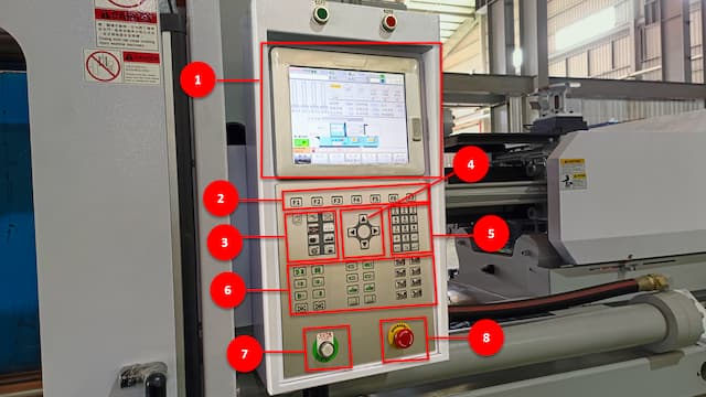
Injection molding machines follow a sequence of connected stages.
During filling, screw velocity controls how the cavity fills, while the available injection pressure must be sufficient to maintain the required velocity. Near the end of filling, V/P switchover transfers control from velocity-controlled filling to pressure-controlled packing. Holding pressure then compensates for material shrinkage while pressure can still be transferred through the gate, after which cooling continues until the part is stable enough for ejection.
Because these stages interact, changing one setting can affect several downstream conditions. For example, increasing melt temperature can reduce melt viscosity and change the pressure required to maintain the same filling velocity. Changing injection speed can also affect the pressure profile and the appropriate V/P transfer point.
That is why you should adjust process parameters in a logical sequence rather than change them randomly.

A practical process development sequence is:
Material and temperature → Plasticizing → Filling → V/P switchover → Packing and holding → Cooling → Repeatability verification
Before adjusting filling pressure or speed, confirm that the basic process conditions are repeatable.
Check:
- Material type and preparation
- Material drying condition where required
- Barrel temperature
- Mold temperature
- Cooling water condition
- Screw recovery
- Shot preparation
- Cushion consistency
Process changes are difficult to evaluate when material condition or temperature is still changing from cycle to cycle.
During plasticizing, back pressure can influence melt homogenization, mixing, screw recovery behavior, and melt temperature. Excessive back pressure may increase shear and plasticizing time, while insufficient back pressure may contribute to inconsistent melt preparation.
The objective is to establish a repeatable melt condition before optimizing the filling stage.
Set the injection speed to achieve consistent cavity filling and an appropriate flow pattern.
Then verify that the machine has sufficient available injection pressure to maintain the required filling velocity.
During velocity-controlled filling, pressure requirements are largely determined by material resistance, part geometry, runner, gate, mold temperature, melt temperature, and selected filling speed. Therefore, the objective is not simply to use the highest possible pressure setting.
A stable filling stage should produce repeatable fill time, screw position, and pressure response over consecutive cycles.
V/P switchover changes the process from velocity-controlled filling to pressure-controlled packing.
The transfer should occur near the end of filling, before excessive cavity pressure develops.
Switching too early can contribute to incomplete filling and unstable part weight. Switching too late can create excessive end-of-fill pressure, flash, or other overpacking-related problems.
Depending on the machine and process, V/P switchover may be controlled by screw position, injection pressure, time, cavity pressure, or another available transfer criterion.
For production machines using screw position as the primary transfer method, evaluate:
- Fill behavior
- Transfer position
- Fill time
- Injection pressure response
- Cushion
- Part condition
The objective is to establish a transfer point that remains repeatable as normal process variation occurs.
After V/P transfer, holding pressure continues packing the cavity and compensates for material shrinkage while pressure can still be transferred through the gate.
Too little holding pressure or insufficient holding time may result in:
- Sink marks
- Voids
- Low part weight
- Dimensional variation
Excessive packing may contribute to:
- Flash
- High residual stress
- Excessive part weight
- Difficult ejection
Use measurable production results such as part weight, critical dimensions, sink marks, flash, cushion, and gate seal behavior to determine a practical operating range.
One useful method for evaluating holding time is to increase it progressively while monitoring part weight. When additional holding time no longer produces a meaningful increase in part weight, the gate may already be sufficiently sealed for that process condition.
After packing becomes ineffective, the part still needs sufficient cooling time to reach a condition where it can be ejected without unacceptable deformation.
Insufficient cooling may cause:
- Warpage
- Ejector marks
- Deformation
- Dimensional instability
Excessive cooling may improve neither part quality nor stability while unnecessarily extending the production cycle.
Because cooling is one component of the total injection molding cycle time, the objective is to use enough cooling for stable ejection without adding unnecessary cycle time.
A process is not stable simply because one molded part looks acceptable.
Run consecutive cycles under normal production conditions and monitor both the parts and the machine data.
Useful indicators include:
- Fill time
- V/P switchover position
- Peak injection pressure
- Cushion
- Screw recovery time
- Part weight
- Critical dimensions
- Cooling time
- Total cycle time
The exact acceptable variation depends on the product specification, material, mold, machine, and quality requirements.
The objective is to confirm that both the process data and molded parts remain within their approved ranges over repeated cycles.
When a defect appears, use the process sequence to identify where the variation is most likely occurring.
| Symptom | Possible Causes | Check First |
|---|---|---|
| Short shot | Melt too cold, low fill speed, early V/P switchover, insufficient pressure capability, restricted flow or venting | Material and temperature, injection speed, pressure response, V/P switchover |
| Flash | Late V/P switchover, excessive packing, high cavity pressure, mold condition, insufficient clamping | V/P switchover, holding pressure, mold and clamp condition |
| Sink marks or low part weight | Insufficient packing, short holding time, early gate freeze, unstable cushion | Holding pressure, holding time, gate seal, cushion |
| Burn marks or weak weld lines | Fill speed, venting, temperature, trapped gas, flow pattern | Injection speed, vent condition, temperature |
| Warpage | Uneven temperature, cooling, packing, material orientation, part or mold geometry | Mold temperature, cooling balance, packing consistency |
| Cycle variation | Plasticizing, recovery, cooling, material condition, or sequence instability | Recovery time, cushion, fill time, temperature, cycle time |
Flash is not always caused by excessive injection or holding pressure. Also evaluate mold parting line condition, vent design, projected area, cavity pressure, and available clamping force in injection molding.
Likewise, do not assume every molding defect is caused by an injection molding parameter. Material preparation, mold condition, venting, gate and runner design, machine capability, cooling system, and product geometry can produce similar symptoms.
A stable process must be repeatable during production and reproducible when the same mold runs again.
Record the approved setup together with the machine, mold, material, and actual production results.
Important records include:
- Material and material condition
- Barrel temperature
- Mold temperature
- Injection speed profile
- Fill time
- V/P switchover position
- Peak injection pressure
- Holding pressure
- Holding time
- Cushion
- Back pressure
- Screw recovery time
- Cooling time
- Total cycle time
- Part weight
- Critical dimensions
For critical applications, additional data such as cavity pressure, cooling water temperature, flow rate, and quality inspection results may also be useful.
Recording both machine settings and actual process results makes it easier to identify what has changed when production begins to drift.
The main injection molding parameters include melt temperature, mold temperature, injection speed, injection pressure capability, V/P switchover, holding pressure and time, back pressure, screw recovery, cooling time, and overall cycle time.
Their interaction is more important than any single setting.
Injection speed determines how quickly the screw moves during velocity-controlled filling. Injection pressure provides the force required to maintain that filling velocity against resistance from the material, runner, gate, and cavity.
If the required pressure reaches the machine’s pressure limit, the machine may no longer be able to maintain the commanded injection velocity. For this reason, evaluate filling speed and available pressure capability together.
No.
The machine needs sufficient pressure capability to maintain the required filling velocity, but setting an unnecessarily high pressure limit does not automatically improve part quality.
The actual pressure required depends on the resin, melt temperature, mold temperature, injection speed, part geometry, runner and gate design, and machine configuration.
Stable injection molding does not come from finding one perfect machine setting. It comes from controlling each stage of the process in a logical sequence and verifying that the resulting parts remain within the required quality criteria.
When troubleshooting, change one process condition at a time and compare both machine data and molded-part results before making the next adjustment.
For machine and process evaluation, Huarong can review your product, material, mold requirements, shot size, production target, and process requirements to help determine a suitable injection molding machine configuration.
- Group Name: Huarong Group
- Brand: Huarong, Yuhdak, Nanrong
- Service Offerings: Injection Molding Machine, Vertical Injection Molding Machine, Injection Molding Automation
- Tel: +886-6-7956777
- Address: No.21-6, Zhongzhou, Chin An Vil., Xigang Dist., Tainan City 72351, Taiwan
- Official Website: https://www.huarong.com.tw/