FOUP vs FOSB: Key Differences and Injection Molding Considerations
2026-10-30 10:18:48
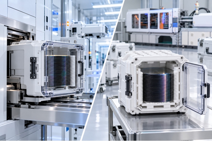
FOUPs (Front Opening Unified Pods) and FOSBs (Front Opening Shipping Boxes) both carry 300 mm semiconductor wafers, but they serve different purposes. FOSBs are primarily designed for shipping wafers between facilities, while FOUPs are used for wafer storage and handling inside semiconductor fabs. For injection molding machine manufacturers and buyers, these differences matter because the molded components, material requirements, mold design, and production conditions determine the appropriate injection molding solution.
The main difference between FOUP and FOSB is their role in semiconductor wafer handling.
A FOSB is primarily a shipping carrier that protects wafers during transport from wafer suppliers to semiconductor manufacturers. A FOUP is designed for wafer storage and movement within semiconductor fabrication facilities, where it interacts with automated material handling systems and process equipment.
| Comparison | FOUP | FOSB |
| Full name | Front Opening Unified Pod | Front Opening Shipping Box |
| Primary purpose | Wafer storage and transport inside semiconductor fabs | Wafer shipping between facilities |
| Typical application | In-fab wafer handling and automated equipment interaction | Transportation from wafer suppliers to semiconductor manufacturers |
| Handling environment | Semiconductor manufacturing facilities | Shipping, receiving, and wafer transfer |
| Main design priorities | Positioning accuracy, equipment interfaces, and dimensional repeatability | Wafer protection, mechanical integrity, and shipping requirements |
| Relevant SEMI standard | SEMI E47.1 | SEMI M31 |
| Injection molding considerations | Precision molded components, interface geometry, and dimensional stability | Injection molded plastic structures, wafer support features, and dimensional consistency |
Although both carriers may contain precision-molded plastic components, their intended applications and engineering requirements differ.
For injection molding machine manufacturers, the key consideration isn't simply whether a component belongs to a FOUP or FOSB. Before selecting a machine, evaluate the actual molded part, resin grade, mold configuration, and production requirements.
A typical 300 mm wafer handling process begins with shipping wafers from a wafer supplier in a FOSB. After a semiconductor fabrication facility receives the shipment, it transfers the wafers into a FOUP or another suitable carrier for subsequent manufacturing operations.

The general workflow is:
Wafer Supplier → FOSB → Inter-Facility Shipping → Fab Receiving → Wafer Transfer → FOUP → In-Fab Handling and Process Equipment
The two carriers serve different stages of this process.
1. Wafer shipping:FOSBs protect wafers during transportation from wafer suppliers to semiconductor manufacturers.
2. Fab receiving and wafer transfer:After receiving and inspection, wafers are transferred from the shipping carrier into a suitable carrier according to the facility's handling procedures.
3. In-fab handling:FOUPs support wafer storage and movement between automated handling systems, equipment load ports, and semiconductor manufacturing equipment.
The exact transfer procedure depends on the facility's carrier system. Some workflows may use a front-opening box for inter-factory transport (FOBIT) or an open cassette instead of a FOUP.
From an injection molding perspective, this distinction helps identify each carrier component's functional requirements. Shipping-related components may prioritize structural integrity and secure wafer support, while in-fab carrier components must also accommodate relevant equipment interfaces and repeated handling.
FOUP and FOSB components may involve different structural designs, molded geometries, and functional requirements. These differences influence how engineers evaluate the injection molding process and select suitable equipment.
The first step is to identify which specific component will be manufactured.
A semiconductor carrier is an assembly, not necessarily a single molded product. Depending on the design, it may contain structural plastic components, doors, wafer supports, seals, and separately manufactured hardware.
Each molded component can have different requirements for:
- Overall dimensions and wall thickness
- Structural strength and mechanical support
- Projected area and cavity configuration
- Critical positioning and assembly features
- Surface quality and dimensional tolerances
Design the mold around the actual component geometry and its functional requirements.
When selecting an injection molding machine, engineers should also verify mold dimensions, cavity layout, platen size, tie bar spacing, mold thickness, and required opening stroke.
For more information, see Huarong's Choosing the Right Injection Molding Machine: A Comprehensive Guide
Material selection depends on the component's mechanical, dimensional, electrical, thermal, and cleanliness requirements.
The selected resin grade directly affects injection molding conditions, including material drying, melt temperature, viscosity, injection pressure, plasticizing capacity, and residence time.
For semiconductor carrier applications, confirm material specifications with the customer and resin supplier rather than assuming them from the carrier’s name.
The injection unit must provide suitable shot capacity and processing capability for the selected material and molded component.
An oversized injection unit is not automatically better. Excessive material residence time can create processing risks, while insufficient injection capacity may affect filling and packing performance.
For more information, see Huarong's Shot Weight Analysis: A Key Factor in Injection Molding Machine Selection.
Dimensional stability matters when molded components must maintain accurate assembly positions, wafer-support geometry, or equipment interfaces.
Several factors can influence the final molded dimensions:
- Material shrinkage
- Filling and packing conditions
- Mold temperature and cooling balance
- Gate and runner design
- Residual stress and ejection conditions
The injection molding machine must provide suitable and repeatable process control so that the validated molding conditions can be maintained during production.
However, dimensional accuracy cannot be guaranteed by machine specifications alone. Part design, material characteristics, mold construction, process optimization, and inspection methods must work together.
For a more detailed discussion of FOUP-specific materials and molding considerations, see Huarong's FOUP Injection Molding Guide: Materials, Process Control and Machine Selection.
No universal injection molding machine tonnage applies to FOUP or FOSB production. Base machine selection on the actual molded component, resin, mold, and production requirements.

The following engineering factors should be reviewed before recommending a machine configuration.
| Evaluation Area | Information to Confirm | Engineering Purpose |
| Component geometry | Part dimensions, wall thickness, projected area, and critical features | Understand the actual molding requirements |
| Material | Resin manufacturer, grade, drying, and processing temperature | Confirm material-processing capability |
| Injection unit | Part weight, runner weight, total shot, screw diameter, injection pressure, and speed | Evaluate injection and plasticizing capacity |
| Clamping unit | Projected area, estimated cavity pressure, and cavity layout | Determine the required clamping force |
| Mold accommodation | Mold dimensions, thickness, weight, platen size, and tie bar spacing | Verify mold compatibility |
| Opening and ejection | Required opening stroke, daylight, ejector arrangement, and robot clearance | Ensure sufficient space for part removal |
| Production requirements | Target cycle time, production volume, and automation requirements | Evaluate the production configuration |
| Quality requirements | Dimensional tolerances, inspection criteria, ESD, and cleanliness requirements | Establish product validation criteria |
Clamping force is an important machine specification, but it should not be the only factor used to determine machine suitability.
A machine may provide sufficient clamping force but still be unsuitable if the mold cannot fit between the tie bars, exceeds the available platen dimensions, or requires a longer opening stroke than the machine can provide.
The injection unit must also match the material and shot requirements. Screw diameter, injection capacity, injection pressure, and plasticizing performance should be evaluated together.
For this reason, always start machine selection with the actual component drawing and mold specifications.
Huarong's Injection Molding Machine Specifications Guide provides further information on the key parameters used in machine evaluation.
For mold accommodation, also refer to Mold Opening Stroke and Thickness: A Guide to Opening Stroke vs Daylight.
To evaluate an injection molding machine for FOUP or FOSB components, buyers should prepare the following information whenever available:
- Component drawing or 3D model
- Resin manufacturer and material grade
- Part weight and estimated total shot weight
- Mold dimensions, thickness, and weight
- Cavity count and runner configuration
- Critical dimensions and inspection requirements
- ESD or cleanliness requirements, where applicable
- Required opening stroke and ejection method
- Automation and robot clearance requirements
- Target cycle time and production volume
These details allow the engineering team to evaluate machine compatibility more accurately.
If the mold drawing or material grade is not yet available, the missing information should be identified before finalizing the machine configuration.
A FOUP is primarily used to store and handle wafers inside semiconductor manufacturing facilities. A FOSB is primarily designed to protect and transport wafers between facilities.
SEMI M31 specifically addresses front-opening shipping boxes for 300 mm wafers and describes the requirements with injection-molded plastic FOSBs in mind. The actual manufacturing method and component design depend on the product specification.
Many FOUP designs include precision molded plastic components. However, a complete FOUP is an assembly, and not every component is necessarily manufactured through injection molding.
Not necessarily. Machine selection depends on the actual molded component, resin grade, mold dimensions, shot requirements, clamping force, and production conditions. The carrier type alone cannot determine the required machine configuration.
Selecting a suitable injection molding machine requires more than knowing whether the target product is a FOUP or FOSB. You must evaluate the molded component, material grade, mold configuration, injection requirements, and quality criteria together.
If you are developing plastic components for semiconductor wafer carriers, you can share your component drawings, resin specifications, mold dimensions, and production requirements with our team for an initial machine suitability evaluation.
- 集團名稱: 華嶸集團
- 品牌: 華嶸、煜達、南嶸
- 服務項目: 射出成型機、立式射出機、成型設備取出裝置
- 服務電話: (06)7956777
- 集團總部: 台南市西港區慶安里中州21之6號
- 官方網站: https://www.huarong.com.tw/