Injection Molding Shrinkage: Causes, Material Factors, and Dimensional Stability Control
2026-05-07 10:11:40
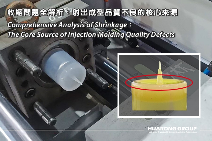
Injection molding shrinkage refers to the reduction in size or volume that occurs when molten plastic cools and solidifies inside the mold. It is a normal material behavior in plastic processing, not always a defect. However, when shrinkage is not properly predicted or controlled, it can cause dimensional deviations, assembly problems, warpage, sink marks, and long-term instability in molded parts.
In practical production, the real challenge is not whether plastic will shrink. The key question is whether the shrinkage is predictable, consistent, and properly accounted for during product, mold, and process design and control.
For manufacturers producing precision plastic parts, shrinkage control is directly related to product quality. It affects tolerance accuracy, flatness, fitting performance, structural stability, and consistency in mass production. Therefore, injection molding shrinkage should not be treated as a simple molding defect. It should be understood as an engineering variable influenced by material behavior, part geometry, mold design, cooling efficiency, and the stability of the injection molding machine.
Shrinkage in injection molding is the dimensional or volumetric reduction of a molded plastic part after the material cools from a molten state to a solid state.
During injection molding, plastic material is heated and plasticized until it reaches a molten, flowable state. After the melt enters the mold cavity, it begins to cool. As the temperature decreases, the molecular chains lose mobility, pack more closely, and occupy less volume. This physical change causes the molded part to become slightly smaller than the mold cavity.
In simple terms:
The difference between the mold cavity dimension and the final molded part dimension results from material shrinkage, process conditions, mold design, and post-molding behavior.
Shrinkage must be considered during mold design. Mold makers usually apply a shrinkage allowance based on resin type, part geometry, flow direction, wall thickness, and expected processing conditions. If shrinkage is underestimated or uneven, the final part may fall outside tolerance even if the mold itself is manufactured accurately.

Shrinkage, sink marks, and warpage are closely related, but they are not the same issue.
Shrinkage is the overall or local size reduction of plastic material during cooling and solidification. It can affect length, width, thickness, volume, and final part dimensions.
Sink marks are visible surface depressions usually caused by localized shrinkage, especially in thick sections, ribs, bosses, or areas with insufficient packing. Sink marks are a surface defect, while shrinkage is the broader physical cause behind many dimensional and appearance problems.
Further Reading: Sink Mark in Injection Molding: Solutions for High-Quality Production
Warpage is the bending, twisting, or deformation of a molded part caused by uneven shrinkage, uneven cooling, residual stress, or directional material behavior. When different areas or directions of the part shrink at different rates, internal stress is released through deformation.
Further Reading: Warpage Analysis in Injection Molding:Influences of Mold, Material, and Processing
A simple way to understand the relationship is:
This article focuses on shrinkage as a dimensional stability issue, not only as a surface defect.
Injection molding shrinkage rate is usually calculated by comparing the mold cavity dimension with the final molded part dimension.
For example, if the mold cavity dimension is 100 mm and the final part dimension is 98.5 mm, the shrinkage rate is:
This formula is simple, but actual shrinkage behavior is more complex. A molded part may not shrink equally in every direction. Shrinkage can vary in the flow, transverse, and thickness directions. It can also vary with gate location, cooling uniformity, material crystallinity, fiber orientation, and packing efficiency.
For this reason, the shrinkage rate should not be treated as a fixed number. It should be evaluated together with the material data sheet, mold flow analysis, part geometry, and actual trial molding results.
Dimensional accuracy is one of the most important reasons manufacturers need to control shrinkage.
If a part shrinks uniformly, the final dimension may still be predictable. The mold can be designed with a proper shrinkage allowance, and the final part can meet the required tolerance. However, if shrinkage is uneven, the part may show dimensional variation even when the mold is properly machined.
Shrinkage-related dimensional problems often appear in the following situations:
- The part becomes smaller than the required tolerance.
- Different cavities produce different dimensions.
- The same mold produces unstable dimensions under different process conditions.
- Assembly gaps become too loose or too tight.
- Large flat parts lose flatness after cooling.
- Thick sections continue to shrink after ejection.
- Parts deform during storage or after a temperature change.
For high precision products, the issue is not only the average shrinkage rate. The real concern is shrinkage consistency. A stable process should produce parts with repeatable dimensions over long production runs.
Shrinkage starts from the molecular behavior of plastic materials.
During the molten stage, polymer molecular chains have higher mobility and greater intermolecular spacing. The material is in a low-density and flowable state. As cooling begins, molecular movement becomes restricted. The chains move closer together, the density increases, and the overall volume decreases.
This behavior becomes more complex when crystallization, glass fiber orientation, fillers, moisture absorption, or residual stress are involved.
Different materials do not shrink in the same way. This is why material selection is one of the most important factors in shrinkage control.
Common amorphous materials include ABS, PC, PS, and PMMA.
Amorphous materials do not form highly ordered crystalline regions during cooling. Their molecular arrangement remains relatively random. Because of this structure, their shrinkage behavior is usually more uniform than that of semi-crystalline materials.
In general, amorphous materials are often selected for parts that require better dimensional stability, surface quality, and cosmetic appearance.
Typical engineering characteristics include:
- Relatively lower shrinkage tendency.
- More predictable dimensional behavior.
- Better suitability for precision or appearance parts.
- Lower risk of crystallization-related deformation.
However, amorphous materials can still shrink and deform if wall thickness, cooling, packing, or mold temperature is not properly controlled.
Common semi-crystalline materials include PP, PE, PA, POM, and PBT.
Semi-crystalline materials form ordered crystalline regions during cooling. As crystallinity increases, molecular packing becomes denser, resulting in higher volume reduction. This makes shrinkage more significant and more difficult to control.
Semi-crystalline materials are widely used because of their mechanical properties, chemical resistance, fatigue resistance, and cost-effectiveness. However, they often require more careful mold design and process control.
Typical engineering characteristics include:
- Higher shrinkage tendency.
- Greater sensitivity to mold temperature.
- More obvious direction-dependent shrinkage.
- Higher risk of warpage and dimensional deviation.
- Possible post-molding dimensional change due to crystallization or moisture absorption.
For these materials, controlling mold temperature, cooling balance, holding pressure, and ejection timing is especially important.
Glass fiber reinforced plastics are commonly used when the part requires higher strength, stiffness, and heat resistance.
Glass fibers can reduce overall shrinkage by restricting polymer chain movement. However, they also introduce directional behavior. During filling, fibers tend to align along the flow direction. This causes different shrinkage behavior in the flow direction and transverse direction.
Typical engineering characteristics include:
- Lower shrinkage in the fiber orientation direction.
- Different shrinkage in the transverse direction.
- Higher risk of anisotropic deformation.
- Stronger relationship between gate design and final part shape.
- Greater need for flow analysis and mold design verification.
Glass fiber-reinforced materials may improve dimensional stability in some cases, but they can also increase the risk of warping if fiber orientation is not properly managed.
Shrinkage is not controlled by a single parameter. It is the result of multiple factors working together.
Material type determines the basic shrinkage behavior. Semi crystalline materials usually shrink more than amorphous materials because crystalline regions form during cooling and increase material density.
Higher crystallinity usually means greater shrinkage. Since crystallinity is affected by cooling rate and mold temperature, the same material may show different shrinkage behavior under different molding conditions.
Wall thickness directly influences cooling time and shrinkage.
Thick sections cool more slowly than thin sections. As a result, thick areas may continue shrinking after thin areas have already solidified. This difference can create internal stress, dimensional deviation, sink marks, or warpage.
Uniform wall thickness is one of the most effective design principles for reducing uneven shrinkage.
The gate controls how melt enters the cavity and how pressure is transmitted during packing.
If the gate is too small or freezes too early, holding pressure cannot continue compensating for material shrinkage. If the gate is located far from thick sections or critical tolerance areas, those regions may not receive sufficient packing pressure.
Good gate design helps improve pressure transmission, reduce local shrinkage variation, and stabilize final dimensions.
Holding pressure is used to compensate for material volume reduction during cooling.
After the cavity is filled, the plastic material continues to cool and shrink. Before the gate freezes, additional melt can still be pushed into the cavity through the holding pressure stage. If holding pressure is too low or holding time is too short, the part may have insufficient packing density.
This can lead to:
- Greater dimensional shrinkage.
- Sink marks in thick sections.
- Voids inside the part.
- Weight variation between shots.
- Poor dimensional repeatability.
Holding pressure should be optimized together with gate freeze time, part weight stability, and dimensional inspection.
Mold temperature affects cooling rate, crystallization, surface quality, and residual stress.
Higher mold temperature can improve surface quality and melt flow, but it may increase crystallinity in semi crystalline materials and lead to greater shrinkage. Lower mold temperature can shorten cooling time, but it may also freeze the surface too quickly and create internal stress.
The goal is not simply to use a high or low mold temperature. The goal is to maintain a stable and balanced mold temperature distribution.
Cooling design is one of the most important mold factors affecting shrinkage.
If one side of the part cools faster than the other side, the two areas will not shrink at the same rate. This difference creates stress imbalance and may cause deformation after ejection.
Balanced cooling helps achieve more consistent shrinkage and better dimensional stability. For large parts, flat parts, and thick wall parts, cooling channel design is especially important.
Injection pressure helps fill the cavity and establish melt pressure. However, pressure decreases as melt flows through the runner, gate, and cavity. Areas far from the gate may receive lower pressure.
If pressure loss is too high, the flow end may have lower packing density and greater shrinkage. This can cause local dimensional deviation, uneven part weight, or weak structural areas.
Pressure transmission should be considered during mold flow analysis and gate design.
If the part is ejected too early, it may not have enough rigidity to maintain its shape. The part may continue shrinking outside the mold, where there is no cavity constraint to support its geometry.
Premature ejection can lead to:
- Post molding deformation.
- Dimensional drift.
- Poor flatness.
- Higher risk of stress release.
Cooling time should be determined based on part thickness, material type, mold temperature, and dimensional stability requirements.

Dimensional deviation occurs when the final molded part does not match the intended tolerance.
This may happen because the shrinkage allowance is incorrect, packing is insufficient, cooling is uneven, or the material behaves differently from the expected shrinkage value.
For precision parts, dimensional inspection should be performed after the part reaches a stable temperature. Some materials may continue changing after ejection due to residual heat, moisture absorption, or internal stress relaxation.
Tolerance instability means that part dimensions change during continuous production.
Possible causes include unstable melt temperature, inconsistent holding pressure, mold temperature fluctuation, material batch variation, or uneven cooling conditions.
This is a serious issue for parts requiring assembly accuracy because even small dimensional changes can affect fit, sealing, movement, or function.
Shrinkage affects how parts fit together.
If shrinkage is too high, holes may become smaller, snap fit features may become too tight, and mating surfaces may lose alignment. If shrinkage varies by direction, the part may twist or become out of square, making assembly difficult.
For products with multiple components, shrinkage control should be considered from the early design stage.
Uneven shrinkage is one of the major causes of warpage.
When different areas of the part shrink at different rates, internal stress is created. After the part is ejected, the stress may be released through bending, twisting, or distortion.
Warpage is often difficult to solve by process adjustment alone. It may require changes in wall thickness, gate location, cooling channel design, rib design, or material selection.
Sink marks are visible surface depressions caused by localized shrinkage and insufficient compensation during cooling.
They often appear behind thick sections, ribs, bosses, or areas where material accumulates. While sink marks are related to shrinkage, they are only one possible result of shrinkage behavior.
Some molded parts continue to change after production.
This may happen due to residual stress release, moisture absorption, secondary crystallization, or environmental temperature changes. Nylon and other hygroscopic materials require special attention because moisture absorption can change part dimensions after molding.
For applications with strict dimensional requirements, post molding conditioning and long term dimensional evaluation may be necessary.
Shrinkage cannot be completely eliminated, but it can be predicted, compensated, and controlled.
Effective shrinkage control requires coordination between material selection, part design, mold design, process settings, and machine stability.
Material selection should consider more than strength, cost, and appearance.
For precision parts, shrinkage behavior and dimensional stability should be reviewed early. Engineers should check the resin supplier’s shrinkage data, understand whether the material is amorphous or semi crystalline, and evaluate whether glass fiber or filler content will affect directional shrinkage.
When changing materials, the original mold shrinkage allowance may no longer be suitable.
Uniform wall thickness helps reduce cooling differences and shrinkage imbalance.
Sudden thickness changes should be avoided where possible. If thick sections are necessary, designers should consider coring, rib optimization, proper boss design, and gradual transitions.
Better part design can reduce the burden on mold and process adjustment.
Gate design should support both filling and packing.
For parts with critical tolerance areas, thick sections, or long flow paths, gate location should be reviewed carefully. The gate should allow pressure to reach important areas before gate freeze. A properly designed gate can reduce pressure loss and improve shrinkage compensation.
For multi cavity molds, balanced filling and packing are essential for dimensional consistency between cavities.
Cooling balance is critical to shrinkage control.
The mold cooling system should provide stable and uniform heat removal across the part. Areas with thick sections, deep ribs, or complex geometry may require additional cooling attention.
Balanced cooling can reduce internal stress, shorten stabilization time, and improve dimensional repeatability.
Holding pressure and holding time should be optimized based on actual part weight, dimensional stability, and gate freeze behavior.
A common method is to observe part weight stability. If part weight continues to increase when holding time is extended, the gate has not fully frozen yet. If part weight becomes stable, additional holding time may not provide further compensation.
The correct holding condition helps reduce excessive shrinkage without creating overpacking stress.
Stable temperature control helps maintain consistent viscosity, flow, packing, and cooling behavior.
If melt temperature fluctuates, material density and pressure transmission may also change. If mold temperature is inconsistent, shrinkage distribution will become unstable.
Temperature stability is especially important for long production runs and precision molding applications.
Mold flow analysis can help predict shrinkage, pressure distribution, fiber orientation, weld lines, cooling balance, and warpage tendency before mold manufacturing.
However, simulation should not replace actual trial validation. The final shrinkage behavior must be confirmed through molding trials, dimensional measurement, and process window testing.
Machine stability plays an important role in shrinkage consistency.
Stable injection speed, injection pressure, holding pressure, screw recovery, melt temperature, and clamping performance all affect repeatability. If machine control is unstable, shrinkage may vary from shot to shot even when the mold and material are correct.
For precision parts, large parts, or thick wall parts, the injection molding machine should provide consistent plasticizing, accurate pressure control, stable clamping, and repeatable process performance.
Shrinkage control is often discussed from the perspective of material and mold design. However, the injection molding machine also plays a key role.
A stable injection molding machine helps maintain consistent processing conditions, which is essential for repeatable shrinkage behavior.
Stable plasticizing helps maintain consistent melt temperature, melt density, and material uniformity. If plasticizing is unstable, the melt entering the cavity may vary from shot to shot, leading to inconsistent packing and shrinkage.
Holding pressure compensates for volume shrinkage before the gate freezes. Accurate holding pressure control helps maintain part weight and dimensional stability.
If holding pressure fluctuates, the part may show different shrinkage levels even under the same mold and material conditions.
Clamping stability affects mold closing, cavity pressure support, and part quality. For larger molded parts, stable clamping is especially important because mold deflection or unstable mold locking can influence part thickness and final dimensions.
A reliable injection molding machine should help manufacturers maintain stable parameters over long production runs. This includes injection speed, pressure, screw position, temperature, cooling time, and cycle consistency.
For manufacturers seeking dimensional stability, machine repeatability is not only a production efficiency issue. It is directly connected to shrinkage control and quality consistency.
Microcellular foam injection molding is often discussed in relation to weight reduction and material savings. However, in many practical applications, one of its important values is improving dimensional stability.
This process introduces supercritical fluid, commonly nitrogen or carbon dioxide, into the molten plastic. After injection into the mold cavity, controlled cell formation occurs inside the part. The internal microcellular structure can help compensate for volume change and reduce the tendency of thick sections to shrink unevenly.
For suitable applications, microcellular foam injection molding may help improve:
- Dimensional stability.
- Sink mark reduction.
- Warpage reduction.
- Weight reduction.
- Material efficiency.
- Lower required clamping force.
- Reduced internal stress in selected part designs.
However, microcellular foaming is not suitable for every product. The final result depends on material type, part structure, surface requirements, mechanical requirements, mold design, and process control capability.
For manufacturers producing thick wall parts, automotive components, structural parts, or products requiring better dimensional stability, microcellular foam injection molding can be evaluated as one possible engineering solution.
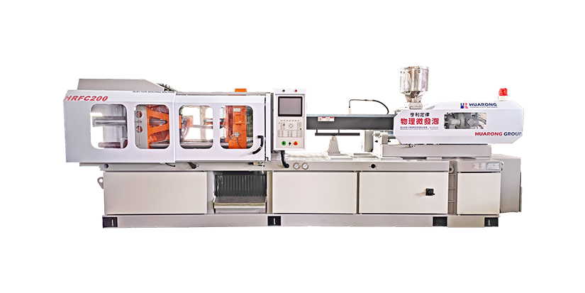
Suggested machine: Microcellular Foam Injection Molding Machine – HRC Series
Shrinkage is unavoidable in injection molding, but it does not have to become an uncontrolled quality problem.
The key is to understand shrinkage as an engineering variable. It is influenced by material structure, crystallinity, filler content, wall thickness, gate design, cooling balance, holding pressure, mold temperature, and injection molding machine stability.
If shrinkage is predicted during product and mold design, compensated during tooling development, and controlled during mass production, manufacturers can improve dimensional accuracy, reduce deformation, minimize surface defects, and achieve more stable production quality.
For plastic part manufacturers, shrinkage control is not only a troubleshooting topic. It is a foundation of dimensional stability, product reliability, and long term molding competitiveness.
- Group Name: Huarong Group
- Brand: Huarong, Yuhdak, Nanrong
- Service Offerings: Injection Molding Machine, Vertical Injection Molding Machine, Injection Molding Automation
- Tel: +886-6-7956777
- Address: No.21-6, Zhongzhou, Chin An Vil., Xigang Dist., Tainan City 72351, Taiwan
- Official Website: https://www.huarong.com.tw/