Two-Shot Injection Molding Defects Troubleshooting:Flash, Weak Bonds, and Vestige Solutions
2026-08-13 14:28:25
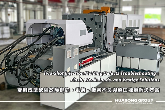
Two shot injection molding defects typically concentrate around three critical areas: the interface between the two materials, the shut-off area of the second shot, and the gate area of the first shot. Flash, weak bonding, and excessive gate vestige rarely have a single cause. Effective troubleshooting requires engineers to evaluate material compatibility, injection parameters, mold design, transfer accuracy, and machine conditions together.
The most common two-shot injection molding defects include flash, weak bonding or delamination, first-shot gate vestige, substrate deformation, short shots, weld lines, and dimensional instability. Compared with conventional injection molding, the two-shot process introduces a second material and an additional molding stage, which means that the first-shot component becomes part of the mold system during the second injection.
A typical two-shot process begins by molding the first material into a substrate. The mold then rotates or transfers the first-shot component to another molding position before the second material is injected. Huarong's HDC Series supports double-shot molding with rotary-table or rotating-shaft configurations for different two-color and two-material applications.
Because the first shot directly affects the second shot, troubleshooting should begin by identifying where the defect occurs and during which molding stage it is created. For example, flash that appears only after the second injection should lead engineers toward the second-shot cavity, shut-off surfaces, substrate deformation, and positioning accuracy. A weak interface, by contrast, requires closer examination of material compatibility and thermal conditions.
| Defect | Typical Location | Main Factors | Initial Troubleshooting Direction |
| Flash | Second-shot edge, shut-off, parting line | Cavity pressure, sealing, alignment | Inspect shut-off and optimize second-shot pressure |
| Weak bond | Material interface | Compatibility, temperature, contamination | Verify material pair and interface conditions |
| Gate vestige | First-shot gate | Gate design, size, location | Review gate position and second-shot coverage |
| Substrate deformation | First-shot component | Cooling, second-shot pressure | Stabilize first shot before transfer |
| Short shot | End of flow path | Speed, pressure, temperature, venting | Check filling and air evacuation |
| Warpage | Overall part | Shrinkage, cooling, residual stress | Balance material and cooling conditions |
These defects can also influence one another. Increasing second-shot temperature may improve bonding but soften the first-shot substrate. Increasing injection pressure may improve filling but increase flash or deformation. For this reason, troubleshooting should focus on identifying the dominant root cause before changing multiple process variables simultaneously.

Flash in two-shot injection molding generally occurs when molten second-shot material enters a gap between the mold and the first-shot substrate. The gap may result from insufficient shut-off sealing, excessive cavity pressure, mold wear, poor alignment, substrate deformation, or inaccurate positioning after mold rotation.
The second-shot shut-off is especially important because the mold must seal against an existing molded component rather than simply against another mold surface. If the first-shot geometry does not provide a stable sealing boundary, molten material can penetrate the interface and form flash. A thin or flexible substrate can create the same problem by deforming under second-shot cavity pressure.
The first step is to determine whether the flash is caused primarily by excessive cavity pressure or inadequate physical sealing. If the mold is correctly aligned and the shut-off structure is sound, reducing second-shot injection speed or pressure incrementally can help determine whether cavity pressure is driving the defect.
Clamping force should not automatically be increased whenever flash appears. If the real problem is worn shut-off steel, substrate deformation, or transfer positioning, additional clamping force will not correct the root cause. Excessive clamping may instead increase mechanical loading on the mold.
A practical troubleshooting sequence is:
1. Confirm that flash occurs during the second shot.
2. Inspect the shut-off surfaces for wear, damage, or contamination.
3. Check mold alignment and rotation or transfer positioning.
4. Inspect the first-shot substrate for deformation.
5. Reduce second-shot injection speed or pressure in controlled increments.
6. If the defect remains, review shut-off geometry and substrate support.
Huarong's technical guidance also emphasizes reviewing injection speed, pressure, mold temperature, mold condition, machine condition, and maintenance when addressing injection molding defects.
A reliable solution is to create a defined and stable sealing structure within the first-shot geometry. Depending on the product, a step, groove, rib, or other controlled shut-off feature can give the second-shot cavity a more predictable sealing boundary.
The second-shot gate location should also be evaluated. If the gate directs high-pressure material toward a thin or unsupported area, the first-shot substrate may deform even when the mold itself is properly aligned. In such cases, modifying the gate location or adding local support can be more effective than simply reducing injection pressure.
For production molds, shut-off wear should also be monitored. A mold that initially produces stable parts can gradually develop flash as sealing surfaces wear or become contaminated. Mold maintenance is therefore part of long-term defect prevention rather than only a corrective action after defects appear.
Weak bonding occurs when the first-shot substrate and second-shot material cannot establish sufficient chemical adhesion, thermal fusion, or mechanical interlocking. Material compatibility should therefore be evaluated before attempting to solve the problem through machine parameter adjustments.
Two polymers may perform well individually but have limited adhesion when molded together. Even when the selected materials are compatible, the interface must reach suitable thermal and surface conditions during the second injection. The condition of the first-shot surface, time between shots, melt temperature, mold temperature, and first-shot cooling can all affect the final interface.
Bonding performance depends on several interacting variables, including material compatibility, resin grade, first-shot surface condition, melt and mold temperature, transfer timing, cooling time, contamination, and second-shot injection conditions. These factors should not be optimized independently because changing one can influence the thermal state and dimensional stability of the first-shot substrate.
The most important process variables are usually second-shot melt temperature, mold temperature, first-shot cooling, transfer timing, and second-shot injection conditions.
If the first-shot surface becomes too cold before the second material reaches the interface, there may be insufficient thermal energy for effective bonding. Increasing the second-shot temperature or mold temperature can sometimes improve adhesion, but these adjustments should remain within the resin supplier's recommended processing window.
The objective should not be to maximize temperature. Excessive thermal energy can soften or deform the first-shot substrate, particularly when it contains thin walls, flexible sections, or unsupported features. A more stable strategy is to identify the minimum practical thermal condition that provides the required bond strength while maintaining dimensional stability.
Injection speed can also affect bonding. A controlled filling profile can provide consistent contact between the second-shot material and the substrate, while excessively aggressive filling can increase cavity pressure and deform the first shot.
When chemical adhesion is limited, mechanical interlocking can provide an alternative retention mechanism. Product designers may incorporate grooves, holes, ribs, undercuts, or other controlled features that allow the second material to physically lock into the first-shot component.
The effective bonding area should also be considered. Increasing the interface area can improve mechanical retention when the selected material combination does not provide strong chemical adhesion.
Surface contamination must also be eliminated as a potential cause. Mold release agents, oil, dust, moisture, or processing residue can create a barrier between the two materials. Resin drying should follow the specific material supplier's requirements.
Bond quality should ideally be evaluated through an appropriate mechanical test rather than visual inspection alone. If the materials separate cleanly at the interface, the interface itself may be the weak point. If one material tears internally while the interface remains attached, the bonding condition may be comparatively strong.
First-shot gate vestige is the residual mark or protrusion left where the first material entered the mold. In two-shot molding, this feature has greater significance because the first-shot component must subsequently be transferred into the second-shot cavity.
An excessive gate vestige can interfere with second-shot mold seating, affect positioning accuracy, become visible on a cosmetic surface, or alter the geometry of the material boundary. Gate design should therefore be considered as part of the complete two-shot product architecture rather than treated as a cosmetic issue after molding.
The most practical approach is to position the first-shot gate where the second-shot material can cover or conceal the vestige. This can turn an unavoidable first-shot gate mark into a hidden feature of the final component.
Gate selection should be evaluated against both molding stages. A gate location that provides good first-shot filling may not be suitable if its vestige interferes with second-shot positioning. Similarly, a gate positioned near a critical shut-off can create additional sealing problems during the second injection.
Depending on product geometry and mold architecture, engineers can evaluate different gate configurations, gate dimensions, and runner arrangements. The appropriate choice depends on the resin, wall thickness, flow length, appearance requirements, and required cycle time.
The key principle is to design the first-shot gate around the final two-shot component, rather than optimizing it only for the first injection.
The most efficient way to troubleshoot multi-shot molding defects is to isolate the problem according to molding stage, defect location, material, mold condition, and machine movement. Two-shot molding contains more interacting variables than conventional injection molding, so changing several parameters simultaneously can make the root cause difficult to identify.
First determine whether the defect occurs at the first-shot gate, second-shot gate, material interface, shut-off, parting line, flow-end region, or a thin-wall section. The physical location provides an important clue about whether the primary issue is related to the material, process, mold, or machine.
The first-shot component should be inspected before the second injection occurs. Dimensions, warpage, gate vestige, surface condition, and substrate stiffness should be checked at this stage. If the first shot is already unstable, modifying the second-shot parameters may only hide the original problem.
The first-shot component must reach the second-shot position consistently. In rotary-table or rotating-shaft systems, even a small positioning variation can influence the material boundary and shut-off condition.
Huarong's HDC Series supports rotary-table and rotating-shaft configurations for different double-injection applications. This type of machine architecture is particularly relevant when the product requires the first-shot component to be transferred between molding positions during the cycle.

For flash, investigate second-shot injection speed, pressure, holding pressure, and shut-off conditions. For weak bonding, prioritize material compatibility and interface temperature before making aggressive machine adjustments. For gate vestige, focus primarily on gate design and location. For substrate deformation, review first-shot cooling and second-shot cavity pressure.
A successful adjustment should be evaluated across multiple consecutive cycles rather than on a single molded part. Depending on the application, engineers should compare dimensions, flash, gate vestige, bond strength, appearance, cycle time, and reject rate before and after the adjustment.
This structured approach also makes troubleshooting easier to communicate between production, tooling, quality, and machine engineering teams.
The most efficient troubleshooting strategy is to determine whether the dominant cause belongs to the machine/process, mold design, or material system. This classification prevents unnecessary tooling modifications when a process adjustment is sufficient, while also preventing repeated machine parameter changes when the real issue is structural.
| Defect | Machine / Process Focus | Mold / Design Focus | Material Focus |
| Second-shot flash | Injection speed, pressure, holding pressure | Shut-off, alignment, substrate support | Melt viscosity and processing window |
| Weak bond | Melt temperature, mold temperature, transfer timing | Bonding area, interlocking structure | Compatibility, surface condition, drying |
| First-shot vestige | Filling and packing conditions | Gate type, size, location | Flow behavior |
| Substrate deformation | Second-shot pressure, speed, cooling | Wall thickness, ribs, gate location | Thermal behavior |
| Short shot | Injection speed, pressure, melt temperature | Runner, gate, venting | Viscosity and processing temperature |
| Warpage | Cooling and process balance | Cooling layout, product geometry | Shrinkage differences |
This framework is useful for deciding whether the next action should be parameter optimization, mold modification, material adjustment, or machine evaluation.
A structured checklist helps production teams avoid changing parameters randomly when a defect appears. The following checks cover the most important variables without replacing application-specific process validation.
- Confirm first-shot and second-shot material compatibility and resin grades.
- Check first-shot dimensions, cooling stability, and gate vestige before transfer.
- Inspect the second-shot shut-off, parting line, and mold alignment.
- Verify rotary-table or transfer positioning repeatability.
- Review second-shot injection speed, pressure, holding pressure, and temperature.
- Check for contamination, moisture, mold release, oil, or residue at the interface.
- Confirm gate location does not interfere with second-shot positioning.
- Verify mold vents and cooling conditions.
- Test bond strength using an appropriate method for the application.
- Compare reject rate, dimensions, appearance, and cycle time before and after adjustment.
The checklist should be used together with controlled trials. If several variables are changed simultaneously, it becomes difficult to determine which adjustment produced the improvement.
Machine configuration affects two-shot molding through injection-unit arrangement, mold transfer method, positioning accuracy, mold dimensions, opening space, and synchronization between the two injection stages. Machine selection should therefore begin with the product and mold requirements rather than clamping force alone.
Huarong's multi-injection machine portfolio includes configurations for double injection, multi-injection, opposite injection, and horizontal rotary-table applications. The HDC Series provides rotary-table and rotating-shaft configurations for different two-color and two-material product structures.
For engineers and procurement managers, machine evaluation should consider the relationship between clamping force, shot weight, mold size, tie-bar distance, mold opening stroke, injection-unit configuration, transfer method, cycle time, automation, and available factory space.
Clamping force alone does not determine whether a machine is suitable. A machine may have adequate tonnage but still be unsuitable if the mold cannot be installed within the available dimensions or if the injection-unit arrangement does not match the product's gate locations and material flow.
The same principle applies to automation. If the production line requires automatic part removal, inspection, material handling, or downstream assembly, these requirements should be considered during machine selection rather than added after the molding process has already been established.
- Required clamping force and shot weight
- Injection-unit arrangement for both materials
- Mold size, tie-bar distance, and opening stroke
- Rotary-table or rotating-shaft requirements
- Positioning repeatability and cycle-time requirements
- Automation and part-removal requirements
- Factory floor space and maintenance accessibility
- Future product or material expansion requirements
Selecting the machine based on the complete production system can reduce the risk of discovering mechanical or automation limitations after mold development has already begun.
Flash is usually caused by a gap between the second-shot mold and the first-shot substrate. Excessive cavity pressure, insufficient shut-off sealing, mold wear, poor alignment, substrate deformation, and positioning errors can all contribute. Inspect the mold and first-shot geometry before simply increasing clamping force.
Weak bonding is commonly related to material compatibility or insufficient interface conditions. Verify the specific resin grades first, then evaluate melt temperature, mold temperature, transfer timing, first-shot cooling, surface cleanliness, and second-shot injection conditions.
Gate location and mold design are usually the most effective areas to address. Positioning the first-shot gate within an area that will later be covered by the second-shot material can help conceal the vestige. Gate geometry and process conditions should also be evaluated according to the product requirements.
No, not in every application. Increasing clamping force can help when mold opening under cavity pressure is the primary cause, but it will not correct worn shut-offs, poor alignment, substrate deformation, or unsuitable injection conditions.
Yes, but mechanical retention may be required. When chemical bonding is limited, grooves, holes, ribs, undercuts, or other mechanical interlocking structures can help retain the second material. The material combination should be validated against the required mechanical, thermal, chemical, and environmental performance.
First compare the current production condition with the last known stable condition. Check whether the material, mold, machine settings, cooling, maintenance status, or rotation and transfer positioning has changed. Then separate first-shot and second-shot defects before changing process parameters.
- Group Name: Huarong Group
- Brand: Huarong, Yuhdak, Nanrong
- Service Offerings: Injection Molding Machine, Vertical Injection Molding Machine, Injection Molding Automation
- Tel: +886-6-7956777
- Address: No.21-6, Zhongzhou, Chin An Vil., Xigang Dist., Tainan City 72351, Taiwan
- Official Website: https://www.huarong.com.tw/