
Injection Molding Machine I/O Signals:Robot, Auxiliary Equipment, and Safety Interlock Guide
2026-05-13 09:08:10
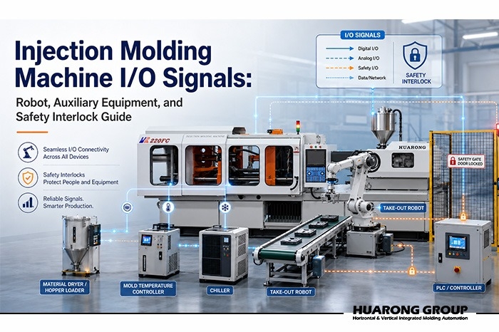
In modern injection molding production, an injection molding machine rarely works alone. It often needs to communicate with robots, conveyors, dryers, auto loaders, mold temperature controllers, chillers, core pullers, inspection devices, reject sorting units, and full automation lines.
This communication depends on I/O signals. I/O means input and output. These signals allow the injection molding machine, robot, auxiliary equipment, and safety devices to confirm status, movement permission, alarm conditions, and safety interlocks.
For many buyers, I/O signals are not the first point they consider when choosing an injection molding machine. They may first focus on clamping force, shot size, screw diameter, platen size, mold height, injection pressure, controller functions, and machine price.
However, after the machine enters production, poor I/O planning can cause serious problems. Common issues include unstable automatic operation, repeated alarms, robot waiting time, incorrect ejector timing, ignoring auxiliary equipment alarms, or bypassing safety interlocks during debugging.
This article explains injection molding machine I/O signals from a practical production viewpoint. It focuses on three key systems:
1. Robot and injection molding machine I/O signals
2. Auxiliary equipment I/O signals
3. Safety interlock and emergency stop logic
The goal is to help buyers, production engineers, automation planners, and molders discuss I/O requirements before the machine is built, installed, and tested.
I/O signals are the input and output signals exchanged between the injection molding machine and external equipment.
1. An input signal is a signal received by the injection molding machine.
2. An output signal is a signal sent by the injection molding machine.
3. An interlock signal is a condition that must be confirmed before a movement is allowed.
In practical terms:
| Signal Type | Meaning | Example |
|---|---|---|
| Input signal | The machine receives information from another device | The robot is outside the mold area |
| Output signal | The machine sends information to another device | Mold is fully open |
| Interlock signal | The machine checks a permission condition before movement | Enable mold closure |
| Alarm signal | A device reports an abnormal condition | Chiller alarm or emergency stop |
These signals allow the machine to know when the robot can enter the mold area, when the mold can close, when the ejector can move, when core pullers are in position, and whether auxiliary equipment is ready for production.
Without correct I/O signals, automation is only mechanical movement without reliable communication.
Injection molding automation depends on correct timing.
1. A robot should not enter the mold area before the mold is fully open.
2. The mold should not close before the robot leaves the mold area.
3. The ejector should not move if the robot, product, or gripper position is not ready.
4. A core puller should not move if it may interfere with the mold, molded part, or robot.
5. A production line should not continue running if a critical auxiliary system has failed.
Therefore, I/O signals serve three major purposes.
I/O signals define the correct order of machine, robot, ejector, core puller, conveyor, and auxiliary equipment movements.
For example, the robot may wait for the mold open signal before entering the mold area. The machine may wait for the mold area to be free before closing the mold.
I/O signals help prevent the machine and robot from moving into the same working space at the wrong time.
However, process interlock signals and safety-related circuits must not be confused. A process interlock helps control the sequence. A safety-related circuit is designed to stop or prevent dangerous movement when a safety condition is not satisfied.
Correct I/O planning reduces random stops, false alarms, part damage, mold damage, robot collision, and unnecessary manual intervention.
For a simple take-out application, I/O signals may only involve the robot and conveyor. For insert molding, overmolding, dual shot molding, automatic assembly, inspection, and packaging, I/O signals become part of the complete production engineering design.

In many injection molding production lines, the robot is the most important external device connected to the injection molding machine.
The robot may perform part take-out, sprue picking, insert loading, stacking, cutting, inspection transfer, or packaging transfer.
To make this work correctly, signals must be exchanged in both directions.
1. Mold Open Signal:The machine sends a mold open signal to confirm that the mold has reached the required open position.
2. Mold Closed Signal:The machine sends a mold closed signal to confirm that mold closing has been completed.
3. Ejector Forward Signal:The machine sends an ejector forward signal to confirm that the ejector has moved forward.
4. Ejector Back Signal:The machine sends an ejector back signal to confirm that the ejector has returned to its safe position.
5. Core Puller Position Signal:For molds with sliders, hydraulic cores, or mechanical core pull structures, the machine may
exchange core position signals with the robot or automation system.
6. Automatic Operation Signal:This signal confirms whether the injection molding machine is in automatic mode or ready
for robot operation.
7. Reject Shot Signal:The reject shot signal is used when the machine identifies a defective shot, an abnormal cycle, or a
process condition requiring product separation.
A robot not only receives signals from the injection molding machine. It must also send confirmation signals back to the machine. These signals are essential for sequence control and interlock logic.
1. Mold Area Free Signal:The mold area free signal confirms that the robot is outside the mold area and does not interfere
with mold opening or mold closing movement.
2. Enable Mold Closure Signal:Enable mold closure gives the machine permission to close the mold.
3. Enable Ejector Forward Signal:The robot may allow the ejector to move forward only when it is in a safe position.
4. Enable Ejector Back Signal:This signal confirms that the ejector can return safely.
5. Robot Ready Signal:Robot ready tells the injection molding machine that the robot program is prepared for automatic operation.
6. Emergency Stop Signal:Emergency stop signals must be treated as safety-related signals, not only normal control signals.
Many injection molding machines and robots use standardized robot interfaces to simplify integration.
EUROMAP 67 is an electrical interface between an injection molding machine and a handling device or robot. It defines signal exchange through electrical contacts, such as relay contacts, switches, and semiconductors. It also provides guidance for plug connections and signal requirements.
SPI AN 146 is a recommended guideline for the Robot and Injection Molding Machine Electrical Interface. It is commonly referenced in discussions of robot and IMM interfaces, especially for projects related to North American standards.
In practical terms, customers should not only ask whether a machine “can connect to a robot.” They should confirm the actual interface standard, robot brand, wiring requirements, safety circuit requirements, and required I/O list before the machine is manufactured.
| Item to Confirm | Why It Matters |
|---|---|
| Robot brand and model | Different robot suppliers may require different wiring or signal logic |
| Robot interface standard | Confirm EUROMAP 67, SPI AN 146, or customer-specific I/O |
| Signal voltage and contact type | Prevent a mismatch between the machine and the robot controller |
| Required safety circuits | Confirm emergency stop and safeguard logic |
| Mold area sequence | Prevent robot and mold movement conflict |
| Ejector and core puller sequence | Prevent interference with gripper, part, or mold components |
Robots are not the only devices that require I/O integration. Many auxiliary systems also exchange signals with the injection molding machine. Auxiliary equipment I/O signals are important because they help prevent production from continuing when material, temperature, cooling, conveying, inspection, or downstream conditions are abnormal.
Further reading:Injection Molding Auxiliary Equipment: A Beginner's Guide
Further reading:Injection Molding Auxiliary Equipment (Part 2): Advanced Systems & Special Processes
Dryers and auto loaders may provide signals such as ready, running, alarm, or low material level.
For stable production, the machine or factory management system may need to know whether the dryer is operating correctly, whether the auto loader has supplied enough material, and whether a material shortage alarm has occurred.
This is especially important for moisture-sensitive materials such as PET, PA, PC, and other engineering plastics. If drying or material supply is unstable, defects may appear as bubbles, splay marks, short shots, weak parts, unstable dimensions, or material degradation.
Cooling and mold temperature control directly affect product quality, cycle time, shrinkage, warpage, and dimensional stability.
Common signals include:
| Equipment | Common Signal | Purpose |
|---|---|---|
| Chiller | Running, alarm, water flow abnormality | Confirms cooling supply condition |
| Mold temperature controller | Ready, temperature alarm, pump alarm | Confirms mold temperature stability |
| Cooling system | Flow confirmation, pressure abnormality | Detects cooling line abnormality |
If the mold temperature controller or chiller is not ready, the machine may still be able to run mechanically, but molded parts may become unstable.
A conveyor may receive a part discharge signal from the machine or robot.
In some systems, the conveyor may also send a full bin signal, jam signal, or stop signal back to the machine.
This prevents parts from piling up, falling, mixing with rejected parts, or blocking downstream production.
In automated molding lines, vision inspection, weight checking, metal detection, or dimensional inspection may send pass or fail results.
The robot or sorting system can then separate acceptable parts from rejected parts.
This creates a more controlled quality flow and reduces the chance that abnormal products enter the next process.
For advanced turnkey systems, the injection molding machine may be connected to assembly stations and packaging systems.
In this case, I/O design must consider not only molding, but also transfer, positioning, assembly confirmation, packaging readiness, and full line stop conditions.
For example, in a fully automated production line, one downstream station alarm may need to pause the entire system to prevent product accumulation.
Not every auxiliary alarm must trigger an immediate emergency stop.
In practice, the response should be defined according to production risk. The response may be alarm only, stop after cycle, hold automatic operation, reject sorting, or full line stop.
For example:
| Auxiliary Alarm | Possible Response |
|---|---|
| Low material level | Alarm or stop after cycle |
| Dryer temperature abnormality | Alarm or stop production for moisture-sensitive materials |
| Mold temperature deviation | Alarm first, stop if outside tolerance |
| Chiller flow alarm | Stop if cooling loss may damage mold or product quality |
| Conveyor full | Stop after the cycle or pause the robot discharge |
| Inspection NG | Reject sorting or production hold based on the quality rule |
This kind of planning helps the production line protect quality without creating unnecessary emergency stops.
The safety interlock is the most critical part of an injection molding automation system.
A safety interlock is a control condition that prevents dangerous movement unless all required safety conditions are satisfied.
In injection molding automation, safety interlocks commonly involve:
| Interlock Item | Purpose |
|---|---|
| Safety door closed | Prevents access to the moving mold area |
| Light curtain OK | Confirms no operator is entering a dangerous zone |
| Mold area free | Confirms the robot has left the mold area |
| Enable mold closure | Allows mold closing only when the sequence is safe |
| Ejector position confirmed | Prevents mold from closing with the ejector forward |
| Core position confirmed | Prevents mold or robot interference |
| Emergency stop circuit | Stops dangerous movements immediately |
| Auxiliary alarm interlock | Prevents production under abnormal auxiliary conditions |
Safety interlocks should not be treated as optional convenience signals. They are part of production safety and equipment protection.
A poor interlock design may allow production to run temporarily, but it increases the risk of mold damage, machine damage, robot collision, product defects, and operator injury.
One common mistake is treating every interlock signal as a safety-rated signal.
In practical production, it is better to separate signals into two groups.
| Signal Type | Function | Example |
|---|---|---|
| Process interlock signal | Controls production sequence | Mold area free, enable mold closure, ejector back |
| Safety-related signal | Stops or prevents dangerous movement | Emergency stop, safety door, light curtain, safeguard circuit |
For example, a mold area free of mold is important for machine and robot sequence control. However, it should not replace emergency stop, safety guard, or other required safety-related circuits.
A safe automation system should use both correct process interlock logic and proper safety-related stop circuits.
During commissioning or mold trial, some teams may temporarily bypass an interlock to test movement.
This must be strictly controlled.
The real risk is not only the temporary bypass itself. The greater risk is that the bypass remains active when the line enters automatic production.
Before full automatic operation, the project team should confirm:
1. All temporary bypass settings have been removed.
2. The emergency stop from the machine can stop the robot.
3. The emergency stop from the robot can stop the machine.
4. Safety door and light curtain signals work correctly.
5. Mold area is free, and the enable mold closure signals are not forced.
6. Ejector and core puller position signals are verified.
7. Alarm reset logic is clearly defined.
This step protects operators, molds, robots, and the production schedule.
Before running the machine in full automatic mode, the following items should be checked one by one.
| Check Item | Why It Matters |
|---|---|
| Signal direction | Confirms whether the signal is from the machine to the robot or the robot to the machine |
| Normally open or normally closed logic | Prevents reversed signal logic |
| Signal voltage | Avoids a mismatch between controllers |
| Dry contact or powered signal | Prevents wiring damage or incorrect input reading |
| Signal duration | Make sure the receiving device can detect the signal |
| Delay time | Avoids robot, ejector, core puller, or mold movement conflict |
| Alarm reset condition | Confirms how the system returns to normal after the alarm |
| Safety circuit response | Confirms emergency stop and safety guard signals work correctly |
| Manual mode behavior | Prevents unexpected robot or machine movement during setup |
| Automatic mode behavior | Confirms full sequence stability before production |
Before purchasing or integrating an injection molding machine, customers should clarify the following information.
List all equipment that needs to communicate with the injection molding machine.
| Equipment | Need for I/O Planning |
|---|---|
| Robot or manipulator | Mold open, mold close, safe position, ejector coordination |
| Conveyor | Part discharge, full bin, jam alarm |
| Chiller | Running status, alarm, flow abnormality |
| Mold temperature controller | Ready, temperature alarm, pump alarm |
| Dryer and loader | Material supply status and alarm |
| Vision inspection | Pass or fail result |
| Assembly machine | Transfer ready and station complete |
| Packaging equipment | Ready, full, stop, alarm |
For robot integration, confirm whether the project requires a standard interface such as EUROMAP 67, SPI AN 146, or a customer-specific I/O arrangement.
This should be confirmed before machine manufacturing, not after the machine arrives at the factory.
The machine supplier and automation supplier must understand the real production sequence.
For example:
Does the robot only take out parts?
Does it load inserts?
Does it wait for ejector movement?
Does it separate the good and rejected parts?
Does it transfer parts to inspection or packaging?
Does the machine need to stop if the downstream equipment is full?
Does the mold have sliders, core pullers, or special ejector actions?
Without sequence confirmation, the I/O list may be incomplete.
Different factories may have different requirements for safety gates, light curtains, emergency stop circuits, robot access zones, electrical standards, and internal safety approval.
These requirements should be discussed at an early stage of the project.
I/O signals should be included in FAT and SAT whenever possible.
During FAT, the manufacturer can verify machine-side functions, robot interface availability, alarms, and basic sequence simulation.
During SAT, the customer site can verify real integration with robots, auxiliary equipment, mold, material, and production environment.
| Check Item | FAT | SAT |
|---|---|---|
| Robot interface wiring | Yes | Yes |
| Mold open and mold closed signals | Yes | Yes |
| Ejector forward and back signals | Yes | Yes |
| Core puller position signals | Yes | Yes |
| Mold area free signal | Yes | Yes |
| Enable mold closure signal | Yes | Yes |
| Emergency stop from the machine to the robot | Yes | Yes |
| Emergency stop from the robot to the machine | Yes | Yes |
| Safety door and guard interlock | Yes | Yes |
| Auxiliary alarm input | Optional | Yes |
| Full automation sequence | Simulation | Real production |
| Reject sorting function | Simulation | Real production |
| Alarm record and troubleshooting | Yes | Yes |
Further reading:Factory Acceptance Test and Site Acceptance Test for Injection Molding Machines: Complete 2026 Guide
Huarong Group provides injection molding machines, vertical injection molding machines, manipulator arms, automation systems, and smart factory management solutions for different production needs.
For customers planning robot integration or turnkey automation, Huarong can assist in evaluating:
1. Machine and mold matching
2. Robot takes out the sequence
3. Auxiliary equipment integration
4. Ejector and core puller control requirements
5. Safety interlock planning
6. FAT and SAT verification items
7. Full line automation feasibility
8. Future production management and monitoring requirements
For simple production, I/O planning may only involve basic robot take-out. For advanced manufacturing processes such as insert molding, dual-shot molding, automatic assembly, inspection, and packaging, I/O planning becomes part of the overall production engineering design.
The injection molding machine's I/O signals are the communication foundation between the machine, robot, auxiliary equipment, and safety system.
They determine whether the machine can work safely with external devices, whether the robot can enter and leave the mold area correctly, whether ejector and core puller movements are coordinated, and whether auxiliary equipment alarms can be handled before they affect production quality.
- Group Name: Huarong Group
- Brand: Huarong, Yuhdak, Nanrong
- Service Offerings: Injection Molding Machine, Vertical Injection Molding Machine, Injection Molding Automation
- Tel: +886-6-7956777
- Address: No.21-6, Zhongzhou, Chin An Vil., Xigang Dist., Tainan City 72351, Taiwan
- Official Website: https://www.huarong.com.tw/

I/O signals are input and output signals used by the injection molding machine to communicate with robots, auxiliary equipment, sensors, safety devices, and automation systems. They help control sequence, confirm movement conditions, and coordinate production actions.
Robot integration requires precise timing between mold opening, robot entry, part take-out, ejector movement, and mold closing. I/O signals confirm each condition so the robot and machine can work together correctly.
Yes. Equipment such as chillers, mold temperature controllers, dryers, auto loaders, conveyors, inspection systems, and sorting devices can exchange ready, running, alarm, stop, or pass and fail signals with the injection molding machine.
Not always. The response should depend on production risk. Some alarms may only require a warning. Some may require a stop after the cycle. Critical alarms may require the machine or the full automation line to stop.

The Huarong Marketing Team is dedicated to translating Huarong’s deep manufacturing expertise into clear, actionable insights for our global audience. By collaborating closely with our R&D and engineering departments, we ensure that every update on injection molding machine technology and industry trends is presented with accuracy and practical value, reinforcing Huarong’s position as a premier injection molding machine manufacturer.
- Expert Insights: Regular updates on injection molding machine optimization and efficiency.
- Proven Reliability: 40+ years as a leading injection molding machine manufacturer in Taiwan.
- Global Reach: Tailored manufacturing solutions for automotive, medical, and packaging sectors.