Comprehensive Analysis of Shrinkage:The Core Source of Injection Molding Quality Defects
2026-05-07 10:11:40
In the injection molding process, shrinkage is an unavoidable but highly controllable physical phenomenon. When plastic material is injected into the mold cavity in a molten state, as the temperature gradually decreases, the kinetic energy of molecular chains declines, and their arrangement changes from loose to compact, resulting in an overall reduction in material volume.
This seemingly simple physical change actually has a profound impact on product dimensional accuracy and structural stability. When shrinkage is inconsistent across different regions or directions, it creates internal stress imbalance within the material, leading to warpage deformation. Therefore, in high-precision product development, shrinkage control is essentially an engineering issue involving the coupling of material, mold, and process, rather than something that can be explained by a single factor.
Further Reading:Sink Mark in Injection Molding: Solutions for High-Quality Production
From a materials science perspective, the root cause of shrinkage is the change in molecular arrangement.
During the molten stage, polymer molecular chains have a high degree of freedom, with large intermolecular spacing, and the material exhibits a low-density, high-flowability state. However, as cooling begins, molecular motion becomes increasingly restricted, and chain segments rearrange into a more tightly packed structure, resulting in a reduction in volume. This effect is especially pronounced in semi-crystalline materials, where crystal structure formation further intensifies volume change, making shrinkage behavior more significant and directionally dependent.
This process can be divided into three stages:
- Melt flow stage:Molecular chains are in a state of high-degree-of-freedom motion, with large intermolecular spacing, and the material exhibits low density and high flowability.
- Cooling solidification stage:Thermal energy gradually decreases, molecular motion weakens, and molecular chains begin to rearrange and pack tightly, increasing density and reducing volume, resulting in shrinkage.
- Stable molding stage:The material may still undergo slight secondary shrinkage due to residual heat or environmental humidity changes, especially in hygroscopic materials (such as polyoxymethylene and nylon).

Different plastic materials exhibit significant differences in shrinkage behavior due to variations in molecular arrangement, which can be categorized into three main types:
Representative materials:Acrylonitrile Butadiene Styrene (ABS), Polycarbonate (PC), Polystyrene (PS)
Structural characteristics:
- Molecular arrangement is randomly entangled
- No crystalline structure forms during cooling
- Volume change is relatively uniform
Engineering characteristics:
- Low shrinkage rate (approximately 0.4% – 0.7%)
- High dimensional stability
- Suitable for high-precision cosmetic and structural parts
Representative materials:Polypropylene (PP), Polyethylene (PE), Polyamide (PA), Polyoxymethylene (POM)
Structural characteristics:
- Formation of ordered crystalline regions during cooling
- Highly compact molecular arrangement
- Significant increase in density
Engineering characteristics:
- High shrinkage rate (approximately 1.2% – 4.0%)
- Pronounced anisotropy (different shrinkage in different directions)
- Prone to warpage deformation
- Higher crystallinity leads to greater volume shrinkage and a higher risk of deformation
Representative materials:Glass fiber reinforced polypropylene, Glass fiber reinforced nylon
Structural characteristics:
- Fibers restrict polymer chain shrinkage
- Flow direction is influenced by fiber orientation
- The coefficient of thermal expansion is significantly reduced
Engineering results:
- Reduced shrinkage in the flow direction
- Increased shrinkage in the transverse direction
- Significant directional differences
In practice, product issues are often not caused by shrinkage itself, but by uneven shrinkage, which can be classified into four typical modes:
This mainly occurs near the gate and at the flow end because pressure transmission of the melt within the cavity is not uniform. Regions close to the gate usually receive sufficient packing pressure, while distant areas tend to suffer from insufficient compensation due to pressure decay. When volume compensation conditions differ across regions, noticeable dimensional differences will occur.
Cooling rates differ between thick and thin sections. Thick sections dissipate heat slowly, resulting in a longer shrinkage duration, while thin sections solidify rapidly. This time lag causes asynchronous volume change in different regions, ultimately leading to stress concentration and dimensional discontinuity at the thickness transition.
During the filling process, molecular chains or fibers are stretched and aligned along the flow direction, forming a distinct directional structure. After cooling, this orientation affects shrinkage behavior, resulting in differences between shrinkage in the flow direction and the transverse direction. This anisotropy is a key source of warpage and deformation.
The mold imposes geometric constraints in the planar direction, preventing free shrinkage, while shrinkage in the thickness direction can still occur. This leads to differences in constraint levels between internal and external shrinkage, causing residual stress accumulation. When the stress exceeds the material’s tolerance, it is released through deformation.
Shrinkage behavior is not governed by a single variable, but is the result of multiple interacting factors:
- Crystallinity:If crystalline structures form during cooling, molecular packing becomes denser, leading to significant volume reduction. Higher crystallinity results in greater shrinkage and more pronounced directional differences, which is why semi-crystalline materials are more prone to warpage.
- Molecular weight:Molecular weight affects melt flowability and pressure transmission capability. Higher molecular weight increases flow resistance, making it difficult for melt pressure to effectively reach the cavity end, resulting in insufficient packing and ultimately causing localized shrinkage and dimensional deviation.
- Glass fiber and filler content:Fillers restrict the free shrinkage of polymer chains, reducing overall shrinkage. However, they also introduce orientation during flow, leading to directional differences in shrinkage behavior. This anisotropy increases the risk of warpage and deformation.
- Gate location and quantity:Gate configuration determines melt flow path and pressure distribution. Poor gate design can lead to insufficient pressure at the flow end and uneven packing, causing localized shrinkage differences and dimensional instability.
- Cooling channel uniformity:The cooling system directly affects mold temperature distribution and heat transfer efficiency. Uneven cooling results in different solidification rates across regions, and this thermal imbalance translates into inconsistent shrinkage and warpage deformation.
- Wall thickness design:Variations in wall thickness cause asynchronous cooling and shrinkage behavior. When thick sections continue to shrink, thin sections may already be fully solidified and constrained by the mold, leading to stress concentration at the transition.
- Venting efficiency:Poor venting leads to gas entrapment, affecting melt filling completeness. Local pressure loss reduces material density, resulting in abnormal shrinkage or dimensional instability in those areas.
- Injection pressure:Injection pressure determines whether the melt can fill the cavity and establish sufficient pressure. Insufficient pressure prevents proper material packing, leading to increased overall or localized shrinkage.
- Holding pressure:The holding pressure stage compensates for volume shrinkage during cooling. If holding pressure is insufficient, material cannot be continuously fed before solidification, resulting in sink marks and dimensional deviations.
- Mold temperature:Mold temperature affects cooling rate and crystallization behavior. Excessively high temperature increases shrinkage, while excessively low temperature tends to freeze residual stress. Both can reduce dimensional stability.
- Cooling time:Cooling time determines whether the material achieves sufficient structural stability. Premature ejection leaves unfinished shrinkage inside the part, leading to subsequent deformation and dimensional drift.
- Wall thickness variation:Uneven thickness causes differences in cooling rates. Thick sections shrink over a longer period, while thin sections solidify quickly. This difference is a primary source of internal stress and deformation.
- Rib design:Ribs usually form localized thick sections, affecting packing and cooling behavior. Improper design can lead to internal shrinkage concentration, manifested as sink marks or stress issues.
- Large flat structures:Flat parts are subject to strong planar constraints in the mold. When shrinkage cannot be freely released, stress accumulates within the structure, ultimately causing overall warpage and geometric deformation.
Dimensional deviations mainly result from incomplete compensation of shrinkage during cooling, especially when packing is insufficient or pressure transmission is uneven. Differences in temperature and pressure conditions across regions lead to inconsistent volumetric shrinkage, ultimately causing parts to fall outside tolerance and affecting assembly accuracy.
The core cause of structural instability is residual stress formed between internal shrinkage and external constraints. This stress is not immediately released after molding. When parts are stored for a long time or exposed to temperature variations, molecular structures continue to rearrange and release stress, resulting in delayed deformation or long-term dimensional drift.
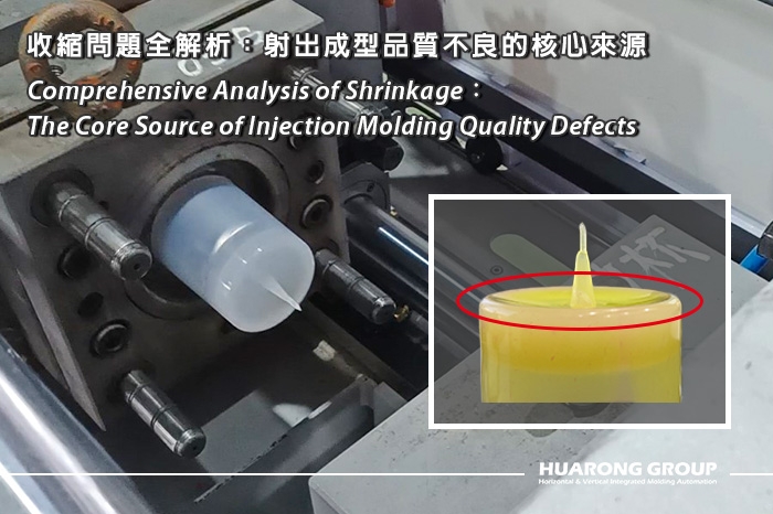
Surface defects are typically caused by rapid local shrinkage combined with insufficient internal packing or feeding, which creates a surface pulling effect. When thickness variation exists, or pressure at the flow end is insufficient, internal shrinkage pulls the surface inward, resulting in sink marks, flow marks, or surface unevenness.
The essence of warpage is the redistribution of stress caused by inconsistent shrinkage across different regions. When differences exist among flow direction, thickness direction, and mold constraint conditions, the material releases internal stress through overall deformation. Such deformation is usually irreversible and is one of the most difficult issues to resolve solely through process adjustments.

From an engineering perspective, shrinkage control is not a single action but the result of overall system optimization. In terms of material selection, amorphous materials typically offer higher dimensional stability, while fiber-reinforced materials can reduce overall shrinkage but introduce directional challenges.
In mold design, uniform wall thickness and balanced cooling systems are the foundation for controlling shrinkage distribution, while gate design affects the uniformity of pressure compensation.
In process control, increasing packing pressure and extending packing time can effectively compensate for volume loss caused by material cooling shrinkage, while balanced cooling rates directly influence residual stress distribution.
In modern engineering, flow analysis and shrinkage simulation technologies are widely applied to predict material behavior before mold manufacturing, thereby reducing trial costs and improving success rates.
Although shrinkage cannot be eliminated, through the integrated optimization of material selection, mold design, and process control, it can be transformed from an uncontrollable error into a predictable engineering variable. The real key is not to eliminate shrinkage, but to ensure its consistency and controllability across different regions and directions. Once shrinkage behavior is incorporated into design logic, product dimensional stability, structural reliability, and mass production consistency will be significantly improved, thereby establishing a truly stable injection molding process capability.
- Group Name: Huarong Group
- Brand: Huarong, Yuhdak, Nanrong
- Service Offerings: Injection Molding Machine, Vertical Injection Molding Machine, Injection Molding Automation
- Tel: +886-6-7956777
- Address: No.21-6, Zhongzhou, Chin An Vil., Xigang Dist., Tainan City 72351, Taiwan
- Official Website: https://www.huarong.com.tw/