Common Injection Molding Defect:Causes and Prevention of Ejector Pin Marks
2026-03-13 11:01:48
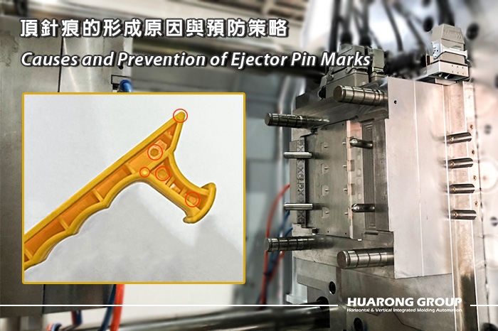
In injection molding production, product appearance directly affects brand image and market competitiveness. Even minor surface defects can cause products to lose advantage in B2B or consumer markets. Among these, ejector pin marks are one of the most common issues. These marks are usually caused by ejector pins or angled ejector rods in the mold exerting pressure on the plastic part surface during demolding. Although ejector pin marks generally do not directly affect the product structure, they may increase local internal stress and even lead to cracks or warpage during use.
Ejector pin marks are traces on the plastic part surface formed by contact with ejector pins or angled ejector rods during demolding. They mainly appear as indentations, gloss variation, whitening, or localized discoloration. Different types of ejector pin marks can have varying effects on product appearance and performance:
| Mark Type | Characteristic | Typical Location | Impact |
| Shallow Indentation | Small depression, circular or flattened shape | Ejector pin contact area | Low impact on appearance if in hidden areas, but excessive concentration may cause stress concentration |
| Whitening | Local surface color lightens or forms a white halo | Pin location and opposite side | May affect product appearance; local stress concentration increases risk of cracking during use |
| Gloss / Color Change | Surface appears glossier or shows color difference | Mold contact area | Affects appearance; structure usually stable, but long-term use requires attention |
Ejector pin marks are not only an appearance issue but also a signal of uneven internal stress distribution, potentially affecting product durability, crack resistance, and long-term reliability.

The causes of ejector pin marks are complex and can generally be divided into two categories:
1. Improper ejector pin placement:If pins are located in thin-wall areas, deep ribs, or easily deformed zones, local force is excessive,
causing indentations or gloss anomalies during demolding.
2. Part not fully cooled:Premature demolding, especially in thick sections, can cause depressions or whitening.
3. Excessive ejection speed or uneven ejection force:High-speed demolding increases local stress, resulting in marks or microcracks.
1. Ejector pins not flush with mold surface:Insufficient machining accuracy or assembly gap causes uneven pin heights, resulting in
localized pressure marks during demolding.
2. Injection and holding pressure too high:Excessive injection pressure increases friction between plastic and mold; excessive
holding pressure can push pins downward or cause deformation.
3. Ejector pins near the gate or insufficient wall thickness:Localized high pressure causes whitening or gloss variation in thin-wall areas.
4. Ejector pins not cooled or uneven mold temperature:Temperature differences cause uneven part shrinkage, forming marks
or stress concentration.
- Appearance quality degradation:For consumer products (e.g., phone cases, food containers), surface defects may reduce market acceptance.
- Localized stress concentration:Whitening or depressions create stress concentration, increasing the risk of cracking or warpage.
- Demolding difficulty:High-friction areas may make parts difficult to demold, increasing machine maintenance costs.

Further reading:Common Injection Molding Defects: Causes, Types, and Solutions
Improving ejector pin marks requires a comprehensive approach that considers product and mold design, process parameters, and material selection.
- Rational pin layout:Distribute pins in ribs, deep cavities, and high-resistance areas to ensure uniform ejection force.
- Optimize gates and runners:Avoid undersized or excessively long runners to reduce flow resistance and internal stress.
- Mold cavity surface treatment:Polishing direction along demolding reduces friction and scratches.
- Mold flow analysis:Predict filling and pressure distribution to assist pin layout and gate design.
- Increase draft angle:Reduce demolding resistance and shorten contact time with pins.
- Control rib and boss height:Reduce local stress and avoid concentrated marks.
- Optimize local wall thickness:Slightly thicken stress-prone areas to improve compression resistance.
| Parameter | Adjustment Strategy | Principle |
| Injection volume | Precisely control to avoid overfilling | Excessive filling increases internal stress and friction, causing marks |
| Injection / holding pressure | Appropriately reduce | Reduce friction between part and pin |
| Injection speed | Reduce or optimize | Reduce turbulence and stress concentration |
| Mold temperature | Appropriately increase | Improve plastic flow and reduce demolding resistance |
| Cooling time / rate | Extend and control uniformly | Avoid whitening caused by rapid local cooling |
| Ejection speed | Maintain within balanced range | Excessive speed increases stress concentration, causing marks |
- Increase pin number and distribute evenly to reduce excessive single-point pressure.
- Control pin tolerance within ±0.03mm to ensure smooth demolding.
- Control pin movement energy and speed to avoid excessive reaction force.
- Use wear-resistant plastics:Nylon, UHMWPE, polyether, etc., to reduce mark visibility.
- Apply mold release agents:Appropriately spray Heat Cure™, Quick Cure, Tuff-Kote, or Dri-Kote to reduce friction and adhesion.
- Uniform cooling design:Use compliant cooling channels to reduce stress caused by temperature differences.
- Sampling inspection:Set sampling ratio based on production volume, e.g., 1 per 100 parts or daily/weekly regular sampling.
- Appearance inspection:Check for indentations, gloss anomalies, or whitening.
- Internal stress inspection:Perform warpage or crack detection if necessary.
- Iterative improvement:Adjust pin layout, process parameters, or mold surface treatment according to inspection results.
Ejector pin marks are usually not caused by a single factor but by multiple conditions acting together. Although these subtle variations may not immediately affect product function, in applications with high appearance requirements or harsh long-term use conditions, they may still pose potential risks to product quality and reliability. Therefore, understanding the formation mechanism of ejector pin marks not only helps improve product appearance but also enhances process stability and quality consistency.
- Group Name: Huarong Group
- Brand: Huarong, Yuhdak, Nanrong
- Service Offerings: Injection Molding Machine, Vertical Injection Molding Machine, Injection Molding Automation
- Tel: +886-6-7956777
- Address: No.21-6, Zhongzhou, Chin An Vil., Xigang Dist., Tainan City 72351, Taiwan
- Official Website: https://www.huarong.com.tw/