Complete Analysis of the Injection Molding Ejection System: Key Technologies from Design to Operatio
2026-02-26 09:41:37
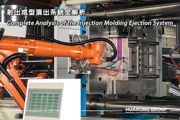
In plastic injection molding, the ejection system is a critical component that ensures smooth part demolding while protecting both the mold and product quality. Although injection pressure, holding pressure, and cooling time are often regarded as the core factors affecting molding quality, neglecting the design and adjustment of the ejection system can lead to part deformation, warpage, ejector pin marks, or brittleness, and may also result in extended cycle times and excessive mold wear.
The core task of the ejection system is to safely demold solidified plastic parts while maintaining the product surface and mold structure. Its design and operation directly affect the following aspects:
- Product integrity:Ensures that parts do not warp, crack, or puncture due to excessive ejection force.
- Mold life:Evenly distributes ejection force, reduces mold wear, and extends service life.
- Production efficiency:Proper ejection stroke and speed settings can shorten cycle time and increase output.
- Automation integration:Synchronizes with robotic arms and conveying systems, reducing manual intervention and production risk.
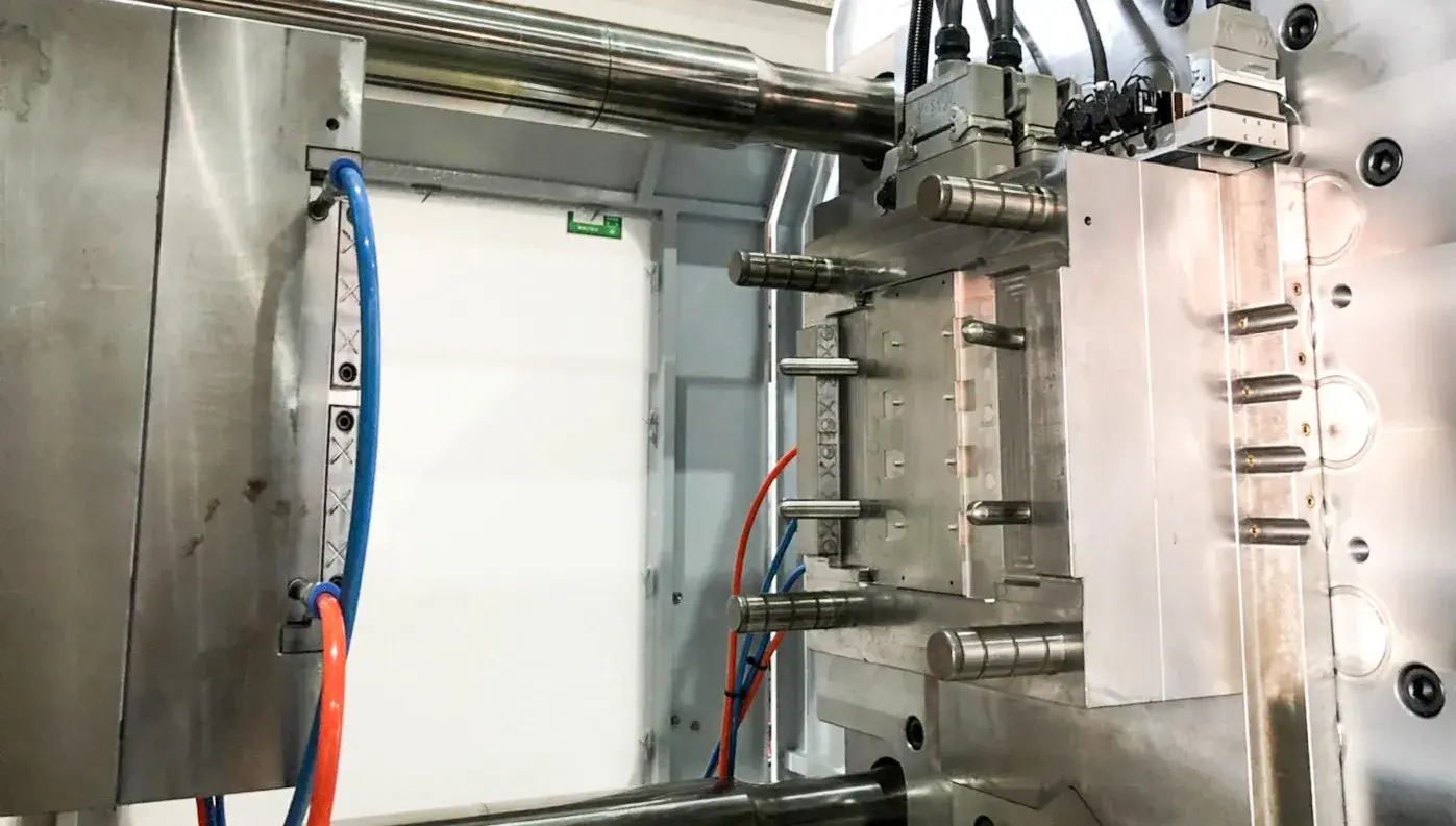
1. Mold opening:The mold separates, and the product begins cooling and prepares for demolding.
2. Ejection activation:The ejection mechanism starts to move forward.
3. Force application for demolding:The product is pushed out of the mold through ejector pins, ejector plates, or air pressure.
4. Product removal:The product completely separates from the mold and is automatically picked up by a robot or collected manually.
5. System return:The ejection mechanism returns to its initial position, the mold closes, and the next cycle is prepared.
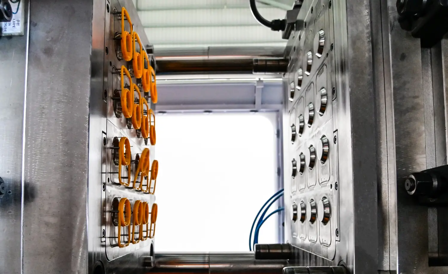
Injection-molded products vary in structure and material. The selection of an ejection system must balance mechanics, surface quality, and production efficiency. Common ejection methods are as follows:
- Characteristics:Most common, simple to manufacture, easy to maintain
- Advantages:Low cost, durable, easy to repair
- Disadvantages:Limited ejection locations; thin-walled or brittle products may leave marks
- Application range:Standard parts, simple molds
- Characteristics:Large flat surface, evenly distributed load
- Advantages:Uniform ejection force, reduced deformation, and surface marks
- Disadvantages:Complex mold structure, high manufacturing cost, prone to wear
- Application range:Automotive parts, large thin-walled components
- Characteristics:Hollow ejector pin used in combination with a sleeve
- Advantages:Large and uniform force-bearing area, inconspicuous marks
- Disadvantages:Complex assembly, prone to wear, high cost
- Application range:Demolding of parts with round holes or blind holes
- Characteristics:Composite ejection combined with ejector pins
- Advantages:Reduces demolding resistance
- Disadvantages:Complex mold structure
- Application range:Deep-cavity sidewall products
- Characteristics:Moves along an inclined surface during ejection to release undercut areas
- Advantages:Can disengage undercut areas and reduce damage
- Disadvantages:Complex design
- Application range:Products with internal recesses or internal undercuts
- Characteristics:Full-perimeter force application
- Advantages:Uniform force on granular or thin-shell parts, reduced deformation
- Disadvantages:High mold cost, complex structure
- Application range:Thin-walled housings, cylindrical parts
- Characteristics:Uses compressed air to assist demolding
- Advantages:Allows demolding at any position, protects the surface
- Disadvantages:Requires additional air supply equipment
- Application range:Large thin-walled parts, sticky parts, auxiliary mechanical ejection
The setup of the ejection system is closely related to mold opening and closing speed. Proper adjustment can shorten cycle time and reduce damage to molds and products.
| Setting Item | Description | Technical Recommendation |
| Fast mold opening | Set according to guide pin and slide separation position | As fast as possible while avoiding mold impact |
| Slow mold opening | Decelerate when approaching the ejection position | Prevent mold drifting and robotic gripping issues |
| Fast mold closing | Move quickly to the low-pressure clamping point | Prevent mold impact and clamp wear |
| Slow mold closing | Complex molds require slower speed to avoid damage | Molds with many slides and ribs need deceleration |
| Low-pressure clamping | Pressure slightly higher than the mold contact point | Prevent material trapping or mold damage |
- Single-stroke ejection:Single-stroke ejection is preferred; multi-stroke ejection increases mold wear by 50%.
- Stroke length:Generally 2/3 of the product depth, or 5 – 10 mm, to ensure sufficient demolding.
- Speed adjustment:
- Complex molds or undercut areas require slow ejection to reduce product damage.
- Thin-walled or standard parts can use faster ejection to shorten the cycle.
- Holding time:For spring ejection or robotic gripping, the ejection holding time can be increased by 0.1–0.5 seconds to ensure smooth product removal.
| Material Type | Recommended Ejection Method | Remarks |
| Rigid plastics (ABS, PP) | Ejector pins / blades | Can withstand high ejection force, suitable for single-stroke demolding |
| Soft / sticky plastics (TPE, TPU) | Lifter / air / ejector plate | Requires low force and avoids surface scratching |
| High-shrinkage materials | High-force ejector pins / air assistance | High shrinkage force requires increased ejection force and auxiliary demolding |
* Supplementary note:Material shrinkage and adhesion are the core factors affecting ejection settings. High-shrinkage materials tend to adhere to the cavity during demolding. If the ejection force or speed is insufficient or inappropriate, warpage, cracks, or mold wear can easily occur. Soft materials require gentle demolding, and air or stripper plate methods can more effectively protect the part surface.
- Identify ejection points:Select areas with high rigidity and non-decorative surfaces as force application points.
- Consider undercut design:Use lifters or angled ejector pins when necessary.
- Design draft angles:Generally 1–2° to facilitate smooth demolding.
- Calculate ejection force and stroke:Ensure sufficient but not excessive force to avoid mold or part damage.
- Material matching:Adjust ejection methods based on material hardness, adhesion, and shrinkage characteristics.
- Integrate automation:Large-scale production can combine robotic arms or air assistance to improve efficiency and stability.
The ejection system is not merely a simple action of “ pushing the product out of the mold ” but a highly integrated mechanical control system. It must be reasonably configured based on product structure, material properties, and mold design in order to stably complete the demolding process without increasing cycle time, and to maximize its value in production.
- Group Name: Huarong Group
- Brand: Huarong, Yuhdak, Nanrong
- Service Offerings: Injection Molding Machine, Vertical Injection Molding Machine, Injection Molding Automation
- Tel: +886-6-7956777
- Address: No.21-6, Zhongzhou, Chin An Vil., Xigang Dist., Tainan City 72351, Taiwan
- Official Website: https://www.huarong.com.tw/