Ejector Stroke Injection Molding: How to Calculate, Set, and Optimize It
2026-02-26 09:41:37
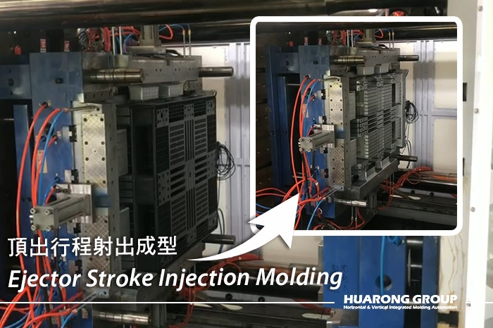
Ejector stroke is the travel distance of the ejector system that pushes the molded part off the core side after the mold opens. It is one of the clamp-side machine specifications that directly affects whether the part can be released smoothly, whether the cycle remains stable, and whether the mold can run automatically without sticking, deformation, or repeated intervention.
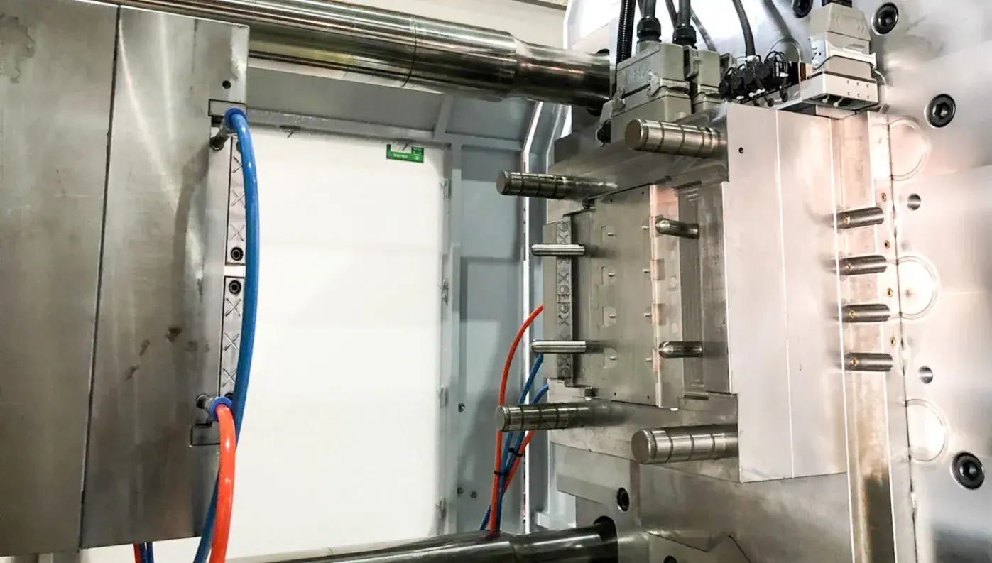
After the part has cooled sufficiently, the mold opens, and the part normally stays on the B-side, where the ejection system is located. The ejector pins, sleeves, stripper plate, or other ejection elements then move forward to release the part, then retract, allowing the mold to close again. Protolabs describes this basic sequence clearly: the pins are located in the B-side mold half, extend after the mold opens, push the part out, and then retract for the next cycle.
This means ejector stroke is not just a machine number on a specification. In production, it defines the usable release travel available to the mold. If the stroke is insufficient, the part may remain partially engaged on the core, drop unpredictably, or fail to clear automation. If it is excessive, ejection can become slower, less stable, or unnecessarily harsh for the part and mold.
Proper ejector stroke affects four critical production outcomes:
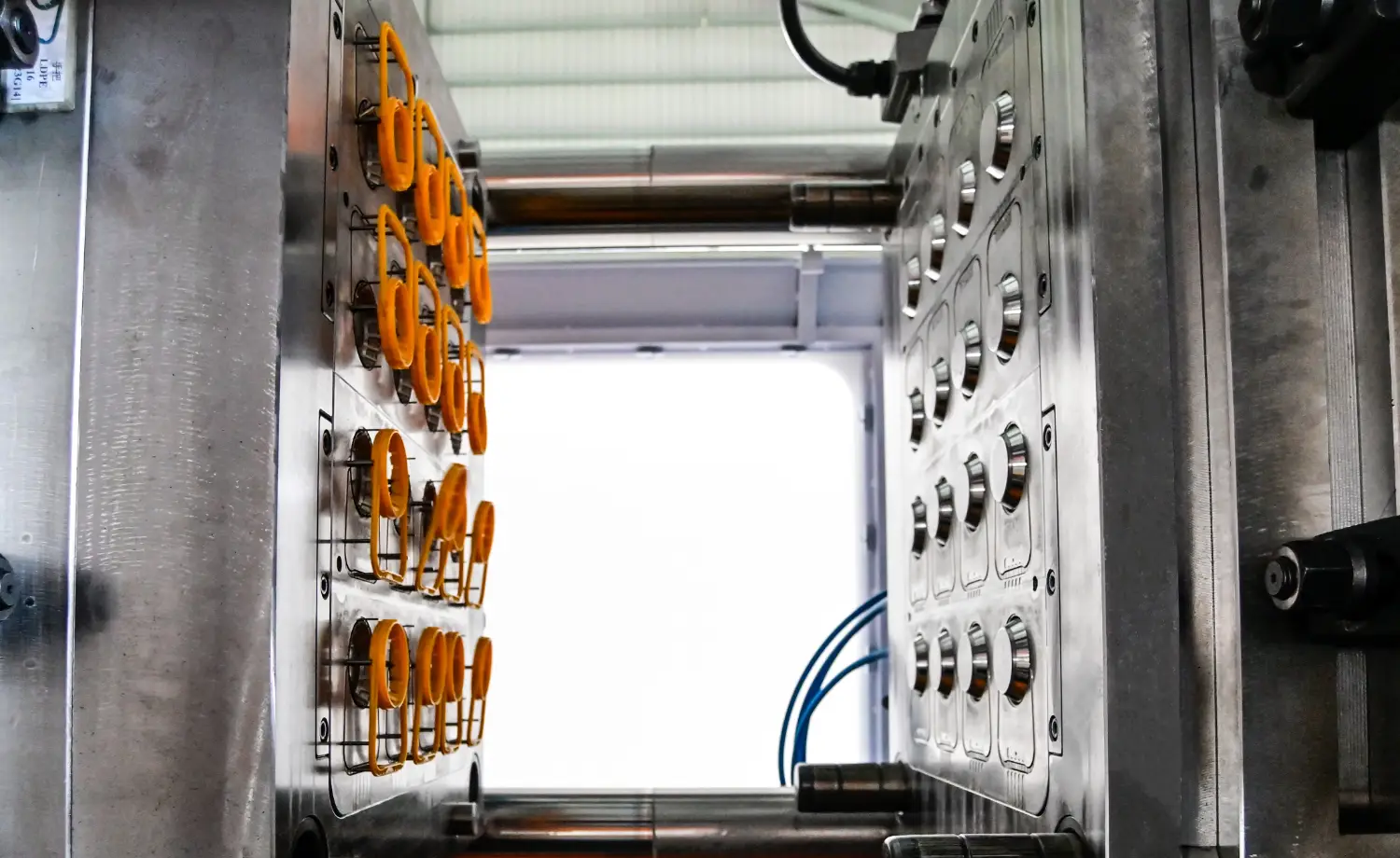
The part must clear the core fully and consistently. If the stroke is too short, the part may hang on textured surfaces, deep ribs, or shrink-fit areas and cause unstable demolding. Protolabs notes that wall depth, rib depth, resin choice, and other design details influence how strongly a part clings to the mold and how the ejection design should be arranged.
Poor ejection can create ejector marks, stress whitening, local puncture, warpage, or cracking.
A suitable ejector stroke helps parts clear the mold quickly and predictably. That improves robot takeout timing, conveyor transfer, and unmanned operation.
Ejection should release the part with enough travel and force, but without repeated overtravel or unnecessary multi-stroke action. Plasticstoday notes that one ejector stroke is generally preferred for part removal and that two strokes can reduce mold life significantly, which is why multi-stroke settings should be treated as a practical compromise rather than a standard default.
These terms are related but not the same.
| Parameter | Simple Meaning | Main Question It Answers |
|---|---|---|
| Ejector Stroke | How far the ejector system moves | Can the part be pushed fully off the core? |
| Ejector Force | How hard the ejector system pushes | Is there enough force to release the part? |
| Opening Stroke | How far the mold opens | Is there enough space to expose and remove the part? |
We should calculate from the actual distance required before the part is free. That usually means reviewing:
- the depth of the part on the core side
- the amount of shrink-fit or adhesion to the core
- whether the mold uses sleeves, stripper plates, or lifters
- whether the robot needs extra lift for reliable takeout
- whether staged ejection or air assist is required
Deep parts, cylindrical parts, covers, housings, and parts with deep ribs often need more careful ejection planning. Protolabs notes that the design and placement of ejector pins must account for how the part will release from the B-side and for the pins' visibility and sensitivity.
Draft does not replace ejector stroke, but it reduces demolding resistance. Protolabs states that a sufficient draft can reduce the need for ejector pins on a part. In practical terms, a better draft reduces sticking and lowers the burden on the ejector system.
If the part contains undercuts or internal retention features, ejector stroke cannot be considered in isolation. Lifters, angled ejection, sleeves, or stripper plates may define the release sequence. The current article already includes lifter ejection, ejector blocks, and stripper plate ejection, which are useful sections that should be retained and connected more directly to stroke selection.
The current article includes a useful list of ejection-system types. That section should be preserved, but revised to show how each type changes the stroke decision.
Round ejector pins are the most common and economical ejection method. They are durable and easy to maintain, but their contact area is limited, so they can leave marks on thin or brittle parts if the force is too concentrated.
Blade ejectors provide a broader contact area and are useful on narrow ribs or rectangular support zones. They can distribute force more evenly than round pins, but mold design and maintenance are more complex.
Sleeve ejection is useful for round bosses, tube-like parts, and features around core pins. It provides a large bearing area and usually leaves less visible ejection marking than a single pin, but the mold structure is more complex and wear control is important.
Ejector blocks help on deep sidewalls or special areas where standard pins do not provide stable support. They can lower local demolding resistance by spreading force over a larger area.
Lifters move along an angled path to release internal undercuts. In these molds, the machine’s ejector stroke must be sufficient not only to push the part, but also to complete the lifter release motion safely.
Stripper plates apply force around the part perimeter and are often preferred for thin-wall housings, cylindrical parts, or parts where pin marks are unacceptable. They usually demand a more deliberate ejection travel plan than simple pin systems.
Air assist can help break vacuum and reduce sticking, especially on large thin-wall parts or sticky materials.
The present article includes useful content on mold opening and closing synchronization, but the stroke section needs stronger engineering framing. A better structure is:
- Open the mold enough to make part release possible and safe.
- Use the minimum ejector stroke that consistently clears the part.
- Adjust ejector speed according to part rigidity, wall thickness, undercuts, and surface sensitivity.
- Add a short holding time only when the part requires stable separation, spring support, or robot pickup confirmation.
- Prefer one clean stroke whenever possible rather than using repeated ejection cycles.
Common symptoms include part sticking, incomplete release, unstable robot pickup, and drag marks on the core side. These problems occur because the part has not traveled far enough to separate fully from the core or textured surfaces.
Excessive travel can add cycle time, create unnecessary impact at the end of travel, or push the part into an unstable drop path. The solution is not maximum travel, but adequate travel with a stable process window.
Check pin location, local wall thickness, part temperature at ejection, and whether the force is concentrated on a decorative or weak area. Protolabs emphasizes correct ejector-pin design and placement because pin marks can be visible if force is applied in the wrong location.
Review whether cooling is sufficient, whether the part is still too soft when ejected, and whether the ejector layout is balanced. A stroke setting alone does not fix a mechanically weak part during demolding. The current article correctly links poor ejection decisions to warpage and deformation.
The ejection system is not merely a simple act of “pushing the product out of the mold ” but a highly integrated mechanical control system. It must be reasonably configured based on the product structure, material properties, and mold design to stably complete the demolding process without increasing cycle time and to maximize its value in production.
- Group Name: Huarong Group
- Brand: Huarong, Yuhdak, Nanrong
- Service Offerings: Injection Molding Machine, Vertical Injection Molding Machine, Injection Molding Automation
- Tel: +886-6-7956777
- Address: No.21-6, Zhongzhou, Chin An Vil., Xigang Dist., Tainan City 72351, Taiwan
- Official Website: https://www.huarong.com.tw/