Core Pull Injection Molding: Engineering Guide to Mechanisms and Process Control
2026-02-13 09:05:46
Core pull injection molding uses movable side actions to form undercuts, side holes, and internal features that cannot release along the main mold opening axis. These movable cores enter the cavity before injection, remain clamped during filling and packing, and retract before the mold opens, allowing the part to be ejected without damage.This article explains the mechanisms and process controls that process control engineers rely on to run core pulls reliably at production scale.
Core pull injection molding adds one or more release directions in addition to the main mold-opening axis. The goal is not merely to “make the undercut.” The goal is to create that geometry with repeatable dimensions, stable surfaces, and a predictable cycle time over hundreds of thousands or millions of shots.
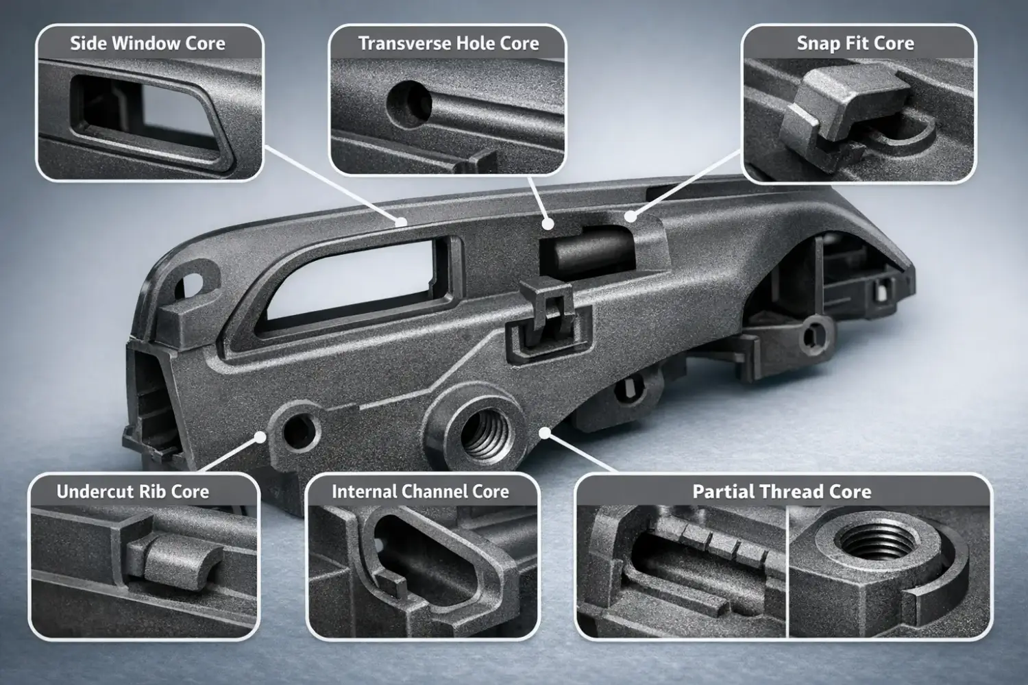
Typical features include side windows, cross holes, snap fits, undercut ribs, internal channels, and partial threads. These often act as functional interfaces, so tolerance and surface finish directly affect assembly yield.
The core must reach full stroke and lock at the end position before injection. It must resist back driving during packing when cavity pressure peaks. Retraction must occur only after the part has sufficient stiffness, drag marks, distortion, or cracks.
After the mold starts to open, the (Hydraulic Cylinder) drives the (Pull Block Main Body) backward. Stage 1 clears the undercut while the (Slide Main Body) stays held, then Stage 2 retracts the (Slide Main Body) further to fully disengage. The key is the moment the undercut becomes free, because it defines the safe switch point between the two stages.
Select the actuation by stroke, required force, mold space, and motion control needs. End position holding must be verified under the expected cavity load.
Hydraulic actuation is commonly used for long strokes, deep undercuts, large core areas, and high-load conditions. Stable production requires reliable end-position holding, typically achieved through mechanical locking features and properly designed hydraulic lock circuits, along with good control of oil temperature, leakage risk, and line routing.
Pneumatic actuation is suitable for short-stroke, moderate-load applications. It is more sensitive to plant air fluctuation and may shift under high cavity load unless the design includes a hard stop or locking strategy. It is often chosen for simpler plumbing and a cleaner mold area when load margins are sufficient.
| Comparison Item | Hydraulic Core Pull | Pneumatic Core Pull |
|---|---|---|
| Driving source | Hydraulic oil pressure | Compressed air |
| Typical use case | Deep undercut, long stroke, high cavity load applications | Shallow undercut, short stroke, moderate load applications |
| Available core pull force | Higher, suitable for resisting high loads during packing | Lower, force limited by air pressure and cylinder size |
| Holding stability under high injection pressure | Stronger resistance to back-driving, better for high injection pressure processes | More likely to shift if cavity load rises, sensitive in high injection pressure conditions |
| Stroke length capability | Typically,easier to support a longer stroke | Typically,better for short stroke, long stroke becomes less stable and slower |
| Motion control and repeatability | Generally stable and repeatable when hydraulic pressure and oil temperature are controlled | Repeatability depends more on-air supply stability and flow control settings |
| Sensitivity to supply fluctuation | Moderate, affected by oil temperature and pressure regulation | Higher, affected by plant air pressure fluctuation and air line restrictions |
| Maintenance focus | Seal condition, oil leakage prevention, temperature control, hydraulic line routing | Air leakage, regulator performance, water removal, airline routing, and flow restriction |
| Cleanliness and environment | Oil leakage risk must be managed | Cleaner operation, no oil leakage concern in the mold area |
| Best quick selection rule | Select the time during which the core must remain stable during packing and at high injection pressure | Choose when the load is modest, and simplicity is a priority |
As product designs diversify, molds often need more slides and side actions. These cores form undercuts, side holes, and hidden functional features in one cycle. In production, the goal is stable motion. The core must reach full stroke. It must remain in place during packing. It must retract within a safe demolding window.
Hydraulic and servo injection molding machines are common choices for these molds. They offer practical interfaces for core pull circuits and control signals. This makes it easier to integrate multiple hydraulic core pulls. Pneumatic core pulls can also be used when the cavity load is modest and the end position is stable.

In many factories, this setup is a balanced option. It supports complex tooling. It is also cost-effective to maintain. Results still depend on mold locking design, guidance, and pressure control.
Suggest Machine: General Injection Molding Machines – HRN Series
Core pull molding is pressure sensitive because cavity pressure becomes a mechanical load on slides and shut-offs.
In core pull injection molding, the machine injection pressure and the cavity pressure are linked but not equal. The mechanical load on the core, slide, and shut-off surfaces is driven by cavity pressure, particularly during packing. The control goal is to use the minimum injection pressure profile that delivers stable fill and packing, while keeping cavity pressure peaks within the holding and guidance capability of the core pull system.
Further Reading: Gas Assisted vs Microcellular Injection Molding – Engineering Comparison of Cavity Pressure Behavior
Injection speed controls shear heating and melt-front stability around core-formed features. A too-fast fill can increase jetting, flow marks, and weld-line weakness where the flow splits and recombines. A too-slow fill can cause early freezing near core restrictions, raising the pressure demand and increasing the risk of short shots.
Switchover should be tuned to avoid overpacking thin areas while maintaining enough packing in thicker regions formed by core pulls. Poor switchover timing often manifests as sink near core features or elevated stress that later manifests as whitening or cracking during undercut release.
Melt temperature affects viscosity and flow resistance, which changes the pressure required to fill and pack the cavity. A small shift in melt condition, such as slightly higher melt temperature or smoother flow, can reduce cavity pressure demand and improve core stability. Mold temperature affects surface replication and the duration of the part's surface remaining soft near the core.
The demolding window is the combination of part stiffness and surface condition during core retraction. If the part is still rubbery, drag marks increase. If the surface is too cold and brittle, whitening or cracking at undercuts becomes more likely, especially in notch-sensitive materials.
Back pressure influences melt homogeneity, density stability, and air entrapment during plasticizing. In core pull injection molding, unstable melt quality can amplify weld line weakness and surface haze near flow splits around core features. Back pressure should be high enough to stabilize plasticizing, but not so high that it overheats the melt or degrades sensitive polymers.
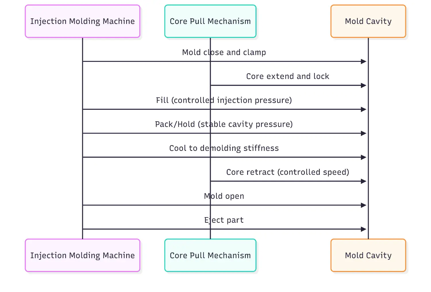
The following sequence summarizes a minimum safe order of operations and the core control checkpoints.
- Mold close and clamp
- Core extend and lock
- Fill with controlled speed and pressure limit
- Pack and hold with stable cavity pressure
- Cool until the part reaches safe demolding stiffness
- Core retract at a controlled speed
- Mold open
- Eject part
Core pull injection molding has characteristic defect patterns. The most reliable troubleshooting method is to separate mechanical causes from process causes, then validate them with evidence of pressure and position.
Common causes are early retraction, rough or contaminated core surface, and insufficient local cooling. Fixes include delaying retraction, reducing retraction speed, improving surface finish or coating, and strengthening local cooling.
Typical causes include deflection, wear, poor guidance, insufficient locking, or excessive cavity pressure. Process-side fixes include reducing pressure peaks through speed profiling, venting improvements, and packing optimization. Mechanical side fixes include shut-off geometry improvement, wear plates, and stronger guidance.
Futher Reading: Flash Injection Molding:Causes, Solutions & Prevention
Often driven by unbalanced filling or asymmetric gating that creates lateral pressure gradients. Runner balance and gate location changes are common root causes, supported by stronger guidance and end-position holding.
This indicates excessive strain during release. Fixes include higher local temperature at release, adding draft or radii, reducing undercut depth, and adjusting the retraction sequence. Notch-sensitive materials may require design changes even with optimized processing.
Hot runners can reduce temperature loss and pressure drop, lowering cavity pressure demand and improving stability around core restrictions. Valve gates support controlled fill sequencing and can reduce hesitation and weld line severity in multi-gate tools. Manifold balance is critical in multi-cavity molds because imbalance shows first around the core-formed features.
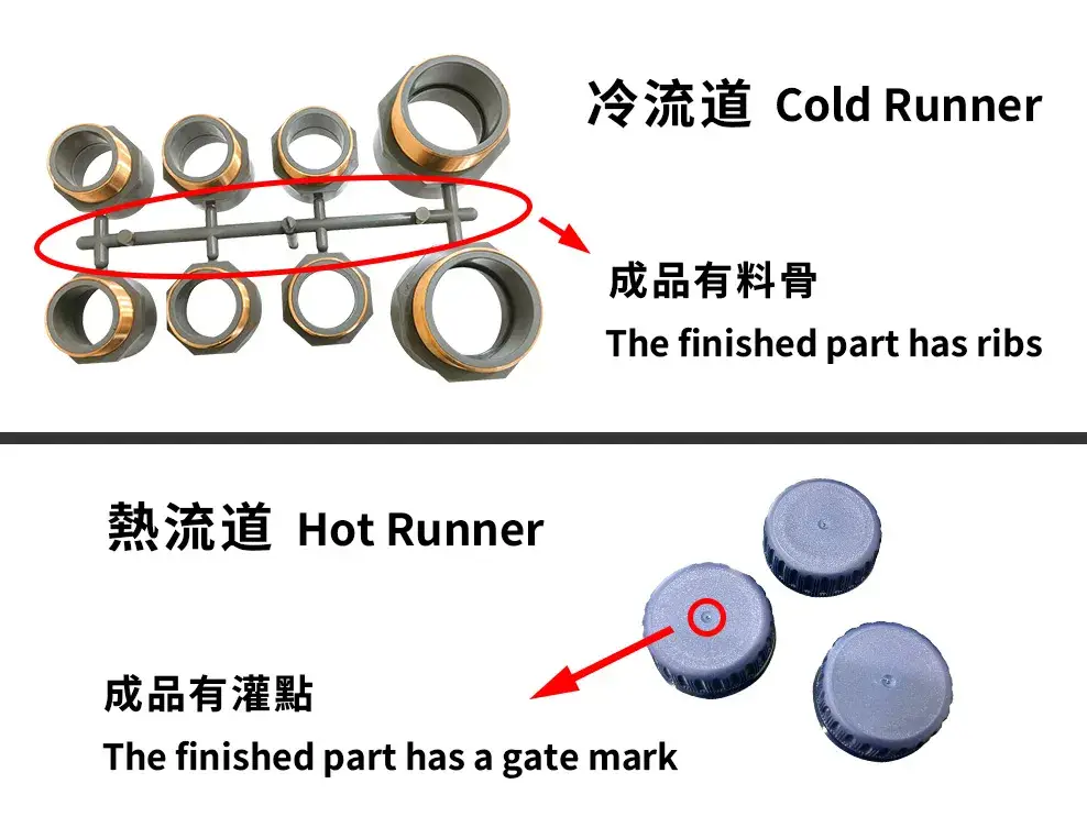
Further Reading: Hot Runner v.s. Cold Runner in Injection Molding: Engineering Comparison & Mold Design Guide
Core pulls deliver value when they replace secondary machining or assembly while maintaining undercut features under real-world factory variation in pressure, cooling, and tool wear. Common use cases include automotive functional housings, fluid components with lateral ports, and consumer parts with hidden snaps where appearance and feel matter.
- Automotive, Connectors, and Functional Housings: Used to form side windows, locking tabs, internal latches, and connector cavities in one cycle, reducing post-processing and improving assembly consistency. Process stability often depends on controlling injection pressure peaks and cavity pressure imbalances, which can deflect slides, shift cores, and cause flash at shut offs.
- Medical and Fluid Components: Applied to internal ports, lateral openings, and flow channels where drilling or manual finishing is undesirable. The main production value is geometry repeatability and a cleaner process flow, achieved through careful control of injection pressure and cooling to reduce residual stress, prevent cracks at undercuts, and avoid drag marks during core retraction.
- Consumer and Cosmetic Parts: Common for hidden snap fits and decorative openings where appearance and tactile quality matter. Production value is achieved by integrating complex features without visible assembly marks, while managing injection pressure profiling, core steel surface finish, and retraction timing to prevent scuffing, gloss variation, and weld line visibility near flow splits.
Core pull injection molding is used to produce parts with undercuts, side holes, internal cavities, and multi-directional geometries that cannot be released from a standard two-plate mold without damage.
Injection pressure loads the core and slide mechanisms during filling and packing. High injection pressure can cause core deflection, flash at shut-offs, and dimensional drift, so pressure must be controlled as both a filling requirement and a mechanical constraint.
We typically choose pneumatic core pulls when the required stroke and pull force are moderate, the undercut is shallow, and the cavity load during packing is low enough that the core will not be pushed back under expected injection pressure. Pneumatic actuation is also preferred when a cleaner mold environment is a priority, oil lines are undesirable, or the application benefits from simpler plumbing and maintenance, provided plant air supply stability can support consistent core positioning.
Hot runners often help by reducing viscosity loss and pressure drop, thereby lowering required injection pressure and improving filling stability around core-created restrictions, especially in multi-gate or complex-geometry molds.
Core pull injection molding enables undercuts, side holes, and internal features in a single cycle. It becomes production-ready only when mold mechanics and process control are designed as one system. Prioritize the right actuation and a reliable end-position holding concept, then confirm rigid guidance and shut-off integrity under peak cavity pressure during packing. On the process side, stabilize fill and switchover to avoid pressure spikes, then tune packing and cooling to hit a repeatable demolding window before core retraction.
Next steps are straightforward. First, validate the core pull sequence and interlocks with the mold open stroke, core position sensors, and a safe retract timing. Second, check cavity pressure behavior, then adjust speed profiling, switchover, and packing to reduce peak load while maintaining dimensional stability. Third, lock in maintenance checkpoints for wear surfaces, lubrication, and hydraulic or pneumatic supply stability. When these items are aligned, core pulls reduce secondary operations, improve yield, and keep cycle time predictable over long runs.
- Group Name: Huarong Group
- Brand: Huarong, Yuhdak, Nanrong
- Service Offerings: Injection Molding Machine, Vertical Injection Molding Machine, Injection Molding Automation
- Tel: +886-6-7956777
- Address: No.21-6, Zhongzhou, Chin An Vil., Xigang Dist., Tainan City 72351, Taiwan
- Official Website: https://www.huarong.com.tw/