Key Role of Holding Pressure:Enhancing Yield and Stable Mass Production
2025-07-10 13:53:19
Holding pressure is the key factor that decides whether molten polymer comes out of the mold as a perfect part or a costly reject. Mastering this stage—located between velocity-controlled filling and final cooling—ensures consistent dimensions, strong mechanical properties, and minimal scrap. Over the next few minutes, you will learn the physics behind holding pressure, data-driven methods for setting time and pressure, advanced multi-stage profiles, sensor-based control, and upcoming Industry 4.0 trends. Use these principles to transform your molding cell from acceptable to world-class.
After ~95 – 98 % volumetric fill, control shifts from velocity to pressure. This lower-than-peak, static force keeps the screw forward until the gate freezes, turning a molten mass into a dimensionally faithful component. Although most designs can use the 95–98 % rule, thin-wall or multi-gate parts often push closer to 98 %, and seasoned processors watch for in-cavity pressure saturation or the moment the screw’s forward advance effectively stops.
This seemingly simple action has four non-negotiable missions:
- Compensate for Cooling Shrinkage: This is its primary purpose. Most polymers shrink as they cool from a molten to a solid state. Holding pressure forces additional melt into the cavity to compensate for this volume loss, fundamentally preventing sink marks and internal voids.
- Ensure Dense Packing: It maintains forward pressure to prevent melt from flowing back through the gate before it solidifies, ensuring the part is fully packed to achieve optimal density and mechanical strength.
- Perfectly Replicate the Mold: It presses the melt firmly against the mold surfaces, allowing it to precisely replicate fine details, textures, and critical dimensions for a flawless finish and tight tolerances.
- Stabilize Molecular Structure: Proper pressure helps to stabilize the orientation of polymer chains, reducing molded-in stress and thereby mitigating post-molding warpage.
The transition from high-speed injection to pressure-controlled holding is the V/P (Velocity-to-Pressure) Switchover. It is one of the most critical settings in the entire cycle, where success is decided in milliseconds.
- Switching Too Early: The holding pressure will be insufficient to complete filling the cavity, resulting in short shots or severe sink marks.
- Switching Too Late: The inertia from the high-speed injection phase creates a massive pressure spike, causing flash and inducing high molded-in stress, which can potentially damage the mold parting line over time.
A precise V/P switchover is timed to occur at the exact moment the cavity is just about full, but not yet packed. In practice, this point is triggered by screw position, hydraulic pressure, or, in advanced setups, in-cavity pressure.
World-class molding operations do not rely on trial and error. Establishing the correct holding parameters is a rigorous, scientific process.
Holding pressure is only effective as long as the gate is open. Applying it after the gate is frozen wastes energy and cycle time. The scientific method to find the precise moment the gate seals is the Gate Seal Study.
Procedure:
- Stabilise all other variables; choose a nominal pressure.
- Start with an obviously short holding time (e.g., 2 s). Record average part weight for 3–5 shots.
- Increase time in fixed increments.
- Plot weight vs time.
The resulting graph will show the part weight increasing with time and then plateauing. The "knee" of this curve, where the weight first stops increasing, is your optimal holding time.
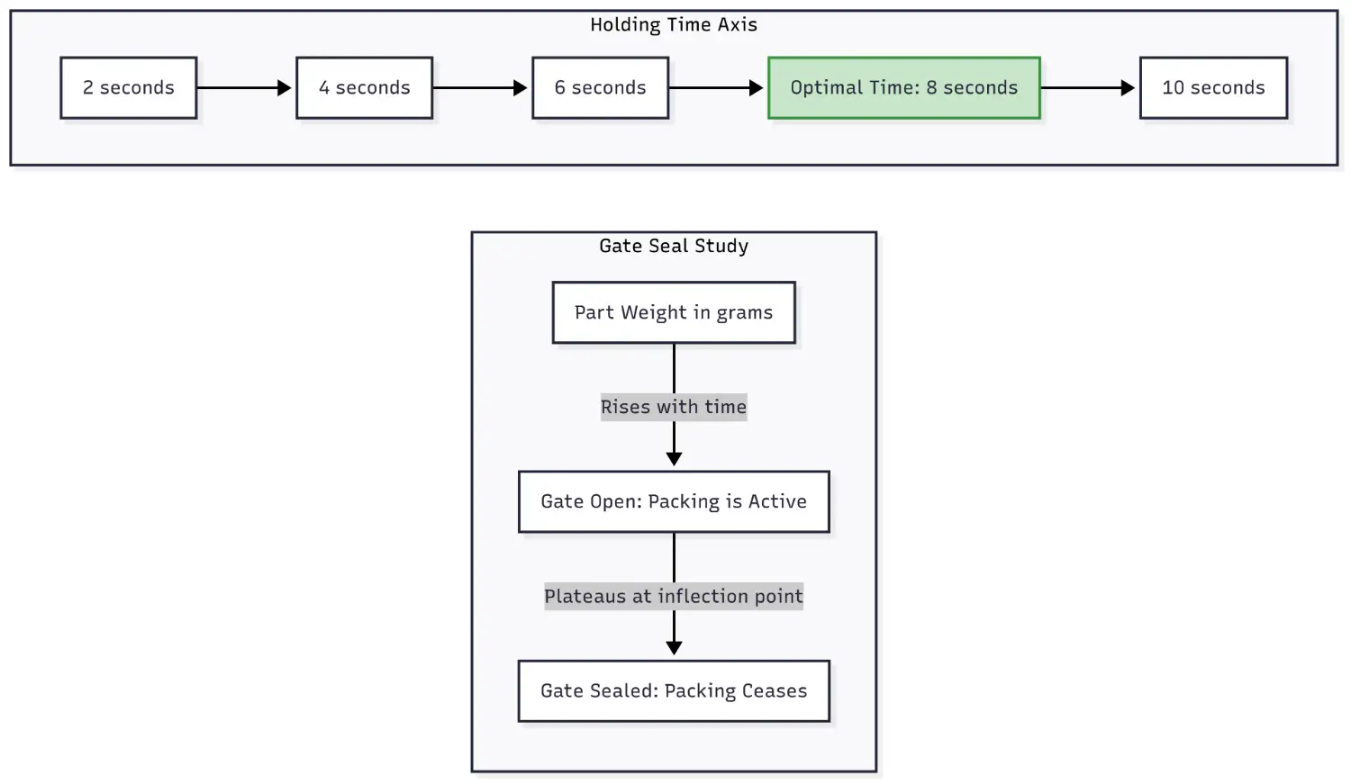
Hold 0.5 – 1 s beyond the gate-seal point to buffer cycle-to-cycle variation. In practice holding time is 30 – 40 % of total cooling time, rising with wall thickness and dropping with higher mould temperatures.
- Lower limit: start low; raise pressure until sinks disappear.
- Upper limit: continue upward until the first flash, sticking, or gate whitening.
- Production set-point: centre of the window (or 60–70 % toward the upper edge if viscosity swings are common).
| Resin | Typical Holding / Peak Injection |
|---|---|
| PP / PE | 30–50 % |
| PA (Nylon) | ≈ 50 % |
| POM | 80–100 % |
For parts with significant variations in wall thickness, a single holding pressure is a compromise. The solution is Multi-Stage Holding.
A typical three-stage profile:
| Stage | Pressure | Purpose |
|---|---|---|
| 1 | High | Pack thick or far-from-gate zones quickly |
| 2 | Medium | Continue shrinkage compensation without over-packing thin walls |
| 3 | Low | Merely hold screw forward until gate freeze, cutting energy |
- Balanced internal stress → less warpage
- Stable part weight/dimensions on thick–thin geometries
- Protects inserts and cores from lateral load
- Lower pump load → energy savings & longer machine life
Improper holding pressure is the root cause of many common defects. This table is your go-to diagnostic tool.
| Defect Observed | Potential Holding Phase Root Cause | Recommended Corrective Action |
|---|---|---|
| Sink Marks / Voids | Holding pressure is below the lower limit, or holding time is shorter than the gate seal time. | Incrementally increase holding pressure. Conduct a gate seal study to set the correct time. |
| Flash | Holding pressure is above the upper limit, or the V/P switchover point is too late. | Reduce holding pressure to the middle of the process window. Adjust the V/P switchover to an earlier position. |
| Warpage / Distortion | Uneven pressure distribution due to part geometry; excessive holding pressure causing high molded-in stress. | Optimize pressure; sometimes a lower pressure reduces stress. Implement a multi-stage holding profile to balance pressure distribution. |
| Dimensional Instability | The process is running at the edge of the process window. | Center the target pressure in the middle of the established process window. Verify and stabilize melt and mold temperatures. |
| Ejector Marks / Sticking | Overpacking the part due to excessive holding pressure or time. | Systematically reduce holding pressure. Verify holding time is not excessively long past the gate seal point. |
Further reading: Common Injection Molding Defects:Causes, Types, and Solutions
Injection molding is moving into Industry 4.0, and holding pressure control is evolving from an art into a data science.
- In-Cavity Pressure Sensing: By embedding sensors directly into the mold, we can monitor the actual pressure of the melt inside the cavity, not just the machine's hydraulic pressure. This technology enables us to disregard variations in machine performance or material viscosity, ensuring that every part is manufactured with an identical pressure profile. It is the ultimate weapon for achieving extreme consistency.
- AI-Driven Automated Adjustment: When combined with AI algorithms, the system can learn from the in-cavity pressure data. If it detects a deviation from the ideal "master curve," it can autonomously fine-tune holding parameters in real-time—before a human operator could even notice a problem—keeping the process perfectly optimized.
Accurate holding pressure turns ordinary moulding into a high-yield, lights-out operation. By combining scientific setup methods, multi-stage profiling, and smart sensor-AI feedback, we, as modern processors, convert holding pressure from a problem child to a profit lever, delivering stable, high-quality output shot after shot.
- Group Name: Huarong Group
- Brand: Huarong, Yuhdak, Nanrong
- Service Offerings: Injection Molding Machine, Vertical Injection Molding Machine, Injection Molding Automation
- Tel: +886-6-7956777
- Address: No.21-6, Zhongzhou, Chin An Vil., Xigang Dist., Tainan City 72351, Taiwan
- Official Website: https://www.huarong.com.tw/