Burn Marks in Injection Molding:Causes and Preventive Solutions
2025-06-19 09:55:09
Learn how to eliminate burn marks from your molded parts and boost product quality through machine tuning, mold design optimization, and material management.
Burn marks (also known as gas burns or dieseling) are black or brown discolorations that appear on molded plastic parts, typically near the end of the flow or in areas where air is trapped. They are caused by high-temperature degradation of the resin or combustion of compressed air in the mold cavity.
Even if minor in appearance, burn marks can:
- Compromise product aesthetics
- Cause structural brittleness
- Lead to rejected parts or customer complaints
- Air not vented properly gets compressed during high-speed injection
- Local temperatures exceed 300°C, igniting air or degrading resin
- High-speed filling compresses air rapidly
- Creates localized overheating and combustion
- Barrel temperature or screw RPM too high
- Degradation of plastic begins inside the injection molding machine
Burn marks tend to occur in:
- End-of-fill zones where the melt stagnates
- Ribs, bosses, enclosed shapes with limited venting
- Corners or dead zones without proper gas release
- Weld lines where two melt fronts meet
Appearance:
- Black or dark brown streaks
- Surface dullness, blistering, or cracking
- In some cases, part weakness or failure
| Inspection Area | Symptom | Recommended Action |
|---|---|---|
| Injection Speed & Pressure | Burn marks near flow ends | Use multi-stage injection, lower final stage speed |
| Mold Venting | Burn marks in corners or bosses | Add venting grooves, vented pins, or porous inserts |
| Melt Quality & Temperature | Burn marks with degraded resin | Lower barrel temps, reduce back pressure and screw speed |
| Material Handling | Use of hygroscopic resin (PA, PET) | Ensure proper drying with desiccant dryers |
| Runner/Gate Design | Burn marks at weld line or end of cavity | Enlarge gate/runner sizes, improve flow balance |
Use mold flow simulation software during mold design to identify:
- Trapped air locations
- Weld line positions
- Pressure and shear zones
Early simulation allows you to adjust venting and runner layout before steel cutting.
Create a database of optimized injection settings by material:
- Injection pressure & speed curves
- Back pressure, screw RPM
- Barrel zone temperatures
This improves repeatability across batches and machines.
- Barrel temperature or screw RPM too high
- Degradation of plastic begins inside the injection molding machine
Implement a preventive maintenance program:
- Regular screw & barrel purging
- Heater band calibration
- Thermocouple inspections
- Raw material storage and inspection
Proactive care reduces downtime and unexpected defects.
Further reading: Common Injection Molding Defects: Causes, Types, and Solutions
Different plastic resins react differently under heat and moisture. Here's how to handle them:
| Material | Risk Factor | Prevention Tip |
|---|---|---|
| PA (Nylon) | Absorbs moisture, prone to outgassing | Dry to <0.2% moisture before molding |
| PET | Very hygroscopic, easily hydrolyzed | Use dehumidifier dryers; dry to <0.05% |
| ABS | Degrades quickly at high temperature | Keep barrel temp below 250°C; avoid long residence time |
| PP | Less hygroscopic but prone to gas traps | Watch for sharp corners or enclosed features |
Avoid using poor-quality masterbatches: Certain black colorants or flame retardants may thermally degrade, contributing to burn marks. Choose high-quality, thermally stable additives.
Further reading: Understanding the 10 Most Common Injection Molding Materials
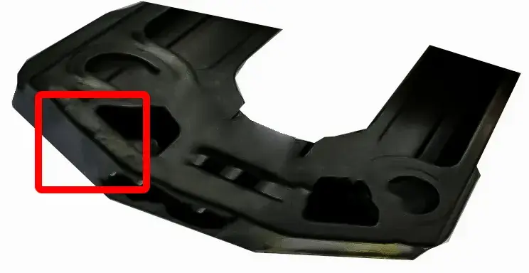
- Good part: Smooth, glossy surface
- With burn mark:
- Black streak at end-of-fill
- Dark spot at rib base
- Cloudy area with discoloration
Every rejected part due to burn marks incurs a hidden cost—in raw material waste, machine downtime, and, most critically, lost customer confidence. Burn marks may seem like a minor surface issue, but they often signal deeper process flaws.
By proactively addressing mold design, machine parameters, material handling, and preventive maintenance, manufacturers can significantly reduce defect rates, improve production consistency, and protect their reputation in competitive markets.
At Huarong, we understand that even the most minor defect can damage both your bottom line and your brand. With over 40 years of experience in injection molding machine manufacturing, we provide stable, energy-efficient, and fully customized solutions tailored to eliminate process defects, such as burn marks, from the start.
Whether you're upgrading legacy systems or setting up a new bright production line, our servo-driven machines. Contact Us to discover how Huarong can help optimize your injection molding process and boost your competitiveness.
- Group Name: Huarong Group
- Brand: Huarong, Yuhdak, Nanrong
- Service Offerings: Injection Molding Machine, Vertical Injection Molding Machine, Injection Molding Automation
- Tel: +886-6-7956777
- Address: No.21-6, Zhongzhou, Chin An Vil., Xigang Dist., Tainan City 72351, Taiwan
- Official Website: https://www.huarong.com.tw/