Injection Pressure in Injection Molding: Complete Guide to Optimizing Quality and Efficiency
2025-06-13 08:45:19

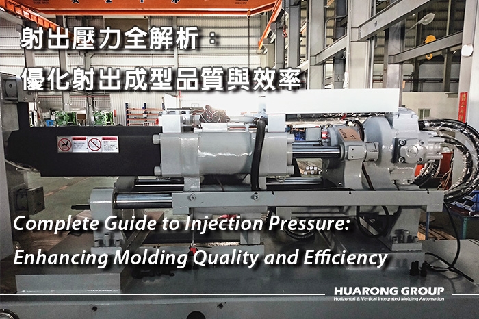
Injection pressure is fundamental in injection molding processes, affecting part quality, cavity filling, material flow, and cycle efficiency. Mastering it at the start of each cycle prevents defects and ensures high-yield, cost-effective production. This guide provides engineers and technicians with insights on controlling, calculating, and optimizing injection pressure to achieve consistent, high-quality output.
Injection pressure refers to the force generated by the screw (or plunger) to push molten injection molding materials through the nozzle, runner, and gate into the mold cavity. It must be sufficient to overcome resistance from part geometry, mold design, material viscosity, and processing speed. The accuracy and stability of this pressure significantly influence product appearance, dimensional integrity, and part repeatability. Underpressure may result in short shots or incomplete fills, while overpressure can cause flashing, internal stress, or mold damage.
Several key factors influence the injection pressure required for a successful molding cycle:
Viscosity, thermal conductivity, and flowability differ by resin type. Semi-crystalline materials such as PA or POM often require higher injection pressure due to rapid solidification and steep changes in viscosity. In contrast, amorphous materials like ABS or PC flow more easily but are more susceptible to overpressure.
Complex geometries, long flow paths, and thin-wall sections increase resistance and require elevated injection pressure. Smaller or improperly designed gates may restrict the flow, unnecessarily raising pressure. A well-balanced runner and gate system helps reduce pressure variation across cavities.
Injection speed, screw design, back pressure during plasticizing, mold temperature, and barrel temperature settings all contribute to pressure behavior. Hydraulic vs. electric machines also influence control precision and maximum pressure capability.
Further reading: Understanding Injection Molding Machine Types: Advantages and Disadvantages of 7 Popular Models
Injection pressure is not constant but changes through different stages of the molding cycle. Each stage plays a unique role in achieving part quality and dimensional stability.
This is the maximum pressure applied during the cavity-filling phase. It must be sufficient to drive molten resin through all flow channels and fill the mold within the desired fill time. Pressure is highest at the start and decreases slightly as the flow front approaches the end of the cavity.
After the cavity is approximately 95–98% filled, the process transitions to holding pressure. This lower but sustained pressure ensures the cavity remains full during cooling and compensates for volumetric shrinkage. If holding pressure is too low or prematurely terminated, sink marks and voids may appear. Overholding, on the other hand, risks overpacking and difficulty with ejection.
Applied on the rear of the screw during plasticizing, back pressure helps ensure melt homogeneity, proper colorant dispersion, and improved melt density. A common setting is 5–20% of primary injection pressure. Excessive back pressure may increase melt temperature and cycle time, while insufficient levels may result in short shots or a poor surface finish.
| Pressure Type | Function | Typical Range |
|---|---|---|
| Primary Injection | Fills cavity with melt | Based on part geometry and material |
| Holding Pressure | Packs material, controls shrinkage | 80–95% of primary injection pressure |
| Back Pressure | Ensures uniform melt during plasticizing | 5–20% of injection pressure |
| Clamping Force* | Keeps mold closed during injection | Based on projected area × fill pressure |
*Clamping force is not a type of injection pressure, but it must resist injection pressure during the filling phase.
Improper pressure settings can introduce various molding defects that compromise functionality, appearance, or dimensional accuracy:
Low injection pressure can prevent the melt from fully entering all mold cavities, resulting in incomplete parts. Solutions include increasing pressure, raising the melt temperature, or improving gate design.
Further reading: Short Shot in Injection Molding: Causes, Detection & Solutions
Excessive injection pressure may force material into parting lines or vents, producing unwanted thin layers of plastic. This can also occur if the clamping force is insufficient.
Caused by underpacking or early termination of holding pressure, these internal and surface defects arise due to material shrinkage. Proper holding pressure and timing help prevent them.
Further reading: Sink Mark in Injection Molding: Solutions for High-Quality Production
Overpressure can cause polymer chains to orient excessively, resulting in residual stress, warpage, and reduced mechanical performance. Balanced pressure settings minimize this risk.
Further reading: Common Injection Molding Defects: Causes, Types, and Solutions
Optimizing injection pressure involves understanding the entire molding system, from raw materials to the limits of the injection molding machine. Here are best-practice strategies:
Use mold flow analysis to predict the areas of highest resistance. Start with high enough pressure to fill the cavity within the intended cycle time, then fine-tune by observing part quality, pressure curves, and short-shot analy
Trigger the transition from injection to holding pressure when the cavity is approximately 95–98% full. This minimizes the risk of overpacking or underfilling. Cavity pressure sensors or scientific molding methods can accurately detect this point.
Speed and pressure are closely linked. High speeds may cause pressure spikes and flow marks, while too slow a fill leads to cold fronts and incomplete filling. Multi-stage velocity-pressure control is crucial for achieving a balance between surface finish and fill balance.
Installing sensors in the mold provides direct feedback on in-cavity conditions, enabling the detection of deviations from the ideal pressure profile and facilitating automatic compensation.
Back pressure, melt temperature, and drying conditions all affect the melt's flow characteristics and required injection pressure. Standardizing these inputs improves process stability and part consistency.
Modern precision molding applications—such as thin-wall components, high-tolerance parts, or multi-gated designs—require more than just a single-stage pressure setting. Multi-stage injection pressure control enables fine-tuning of pressure throughout the fill phase, enhancing flow consistency and reducing defect rates.
The melt's flow behavior changes dynamically as the cavity fills. Early-stage resistance may be higher due to long flow paths, while final-stage risks include overpacking, jetting, or flash. A uniform pressure across the entire fill phase can result in inconsistent part dimensions, visible flow lines, or residual stress.
By breaking the injection phase into multiple stages, each with tailored pressure and speed settings, engineers can:
- Prevent flow hesitation in narrow or intricate regions
- Avoid overpressure in short flow sections
- Improve cavity balance in multi-gate or family molds
- Reduce weld lines and minimize internal stress
A common 3-stage setup includes:
- Stage 1: Moderate pressure to initiate stable flow and avoid jetting
- Stage 2: Increased pressure to drive flow through complex geometries
- Stage 3: Reduced pressure to control the final fill and minimize flash
Transitions between stages can be triggered by:
- Screw position (e.g., 30 mm → 15 mm → 5 mm)
- Time-based intervals (e.g., 100 ms → 250 ms)
- Real-time cavity pressure sensor feedback
Pressure profiles must align with speed profiles. As pressure increases or decreases, corresponding changes in velocity ensure stable melt front behavior. This coordination avoids turbulence, burn marks, or flow stagnation.
Servo-driven injection molding machines offer precise control for multi-stage settings. Machines equipped with closed-loop feedback and in-mold sensors can automatically adjust pressures based on real-time cavity data, ensuring consistent part quality across high-volume runs.
Suggested machine: Servo Injection Molding Machines – HRS & HRFC Series
Injection pressure is a key parameter in injection molding, affecting material flow and the quality of the final part. By mastering the relationship between pressure, speed, material behavior, and tooling design, manufacturers can produce high-quality parts with fewer defects, shorter cycle times, and lower costs. A disciplined method utilizing data, tooling optimization, and sensor feedback enables injection pressure to enhance performance, efficiency, and product excellence.
- Group Name: Huarong Group
- Brand: Huarong, Yuhdak, Nanrong
- Service Offerings: Injection Molding Machine, Vertical Injection Molding Machine, Injection Molding Automation
- Tel: +886-6-7956777
- Address: No.21-6, Zhongzhou, Chin An Vil., Xigang Dist., Tainan City 72351, Taiwan
- Official Website: https://www.huarong.com.tw/


