


FOUP Injection Molding Guide: Materials, Process Control and Machine Selection for 300 mm Wafer Carr
2026-09-23 11:00:13
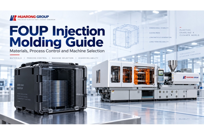
A FOUP may look like a plastic enclosure, but molding components for semiconductor wafer handling involves much more than producing a large plastic part. Material behavior, dimensional stability, wafer positioning, electrostatic discharge control, contamination, automation interfaces, and repeatable molding conditions can all affect performance.
From an injection molding machine manufacturer’s perspective, one principle comes first: the machine should be selected from the actual molded component, resin, mold, and process requirements, not from the product name alone. Huarong applies the same engineering logic when reviewing machine configuration, including shot size, screw selection, residence time, and clamping requirements. Read our injection machine selection guide.
No universal technical rule states that FOUP production must use a 2,000- or 3,000-ton machine. Required clamping force and machine size depend on the actual molded component, projected area, cavity pressure, mold envelope, and process conditions.
H2:What Is a FOUP?
FOUP stands for Front Opening Unified Pod. It is a carrier used to transport and store 300 mm wafers in semiconductor manufacturing facilities. Common configurations include 25-slot and 13-slot designs, depending on the wafer and handling requirements.
A FOUP works as part of a larger automated environment. It interfaces with automated material handling systems (AMHS), overhead transport systems (OHT), equipment load ports, and robotic wafer handling. SEMI standards define many of these physical interfaces so that carriers and fab equipment can work together consistently.
This is why dimensional stability matters. A FOUP is not only a storage enclosure. Carrier geometry must remain compatible with wafer positioning, load-port placement, and automation interfaces.
H2:Which FOUP Components Are Injection Molded?
Not every FOUP part should be treated as one injection-molded component. Public technical sources document precision-molded FOUP inserts, wafer cassettes, and semiconductor wafer carriers. These components may use engineering plastics such as PEEK or static-dissipative compounds to combine dimensional stability with wafer-handling performance.
Large structural parts such as shells and door components are also produced from engineering plastics in commercial FOUP platforms. However, detailed mold information such as wall-thickness distribution, gate design, projected area, shot weight, and mold construction is usually proprietary. Check these values from the actual part and mold rather than estimating them from the assembled FOUP dimensions.
Other items, including seals, RFID tags, purge fittings, fasteners, and metallic hardware, may be separately manufactured and assembled. For machine selection, the first question is therefore simple: Which specific component will be molded?
H2:What Materials Are Used in FOUP and Wafer Carrier Components? (還沒看完)
#圖片插入: (英文) https://i.meee.com.tw/y7fMdNP.webp

#圖片插入: (中文) https://i.meee.com.tw/ozlltFY.webp

There is no single “FOUP plastic.” Material selection depends on the component, wafer-contact requirement, ESD performance, dimensional stability, temperature resistance, and contamination target.
| Material System | Application Example | Key Molding Consideration |
|---|---|---|
| PC | Structural carrier components | Drying, residual stress and dimensional stability |
| Conductive / carbon-filled PC | Static-dissipative structures | Flow consistency, surface quality and ESD performance |
| PEEK / PEEK ESD | Wafer-contact parts and wafer carriers | High processing temperature and dimensional control |
| PEEK with carbon fiber | Precision wafer-handling components | Fiber orientation, anisotropic shrinkage and warpage |
| PEI / conductive PEI | Semiconductor carrier components | Thermal and dimensional requirements |
| Barrier materials / CNT systems | Contamination-sensitive carrier platforms | Material-specific processing and contamination performance |
Important: PC, PEEK and conductive compounds should not be treated as having one universal processing window. Drying, melt temperature, mold temperature, residence time and injection settings must follow the actual resin grade and material supplier recommendations.
For the injection molding machine, the resin can affect barrel temperature capability, screw and barrel configuration, injection pressure demand, and plasticizing stability. Evaluate shot capacity alongside screw diameter and residence time, rather than as an isolated specification. See Huarong’s machine selection guide.
H2:What Makes FOUP and Wafer Carrier Injection Molding Difficult?
H3:Dimensional Stability and Wafer Positioning
Wafer-support geometry can be sensitive to molding variation. In one published study of a 25-slot PEEK/carbon-fiber semiconductor wafer carrier, process optimization reduced the reported pitch standard deviation from 0.1095 mm to 0.022 mm. The value is application-specific, but the engineering lesson is clear: molding conditions can directly affect carrier geometry.
Treat shrinkage as a dimensional-control variable, not just a material datasheet number.
Further reading: Injection Molding Shrinkage and Dimensional Stability Control.
H3:Warpage and Residual Stress
Uneven filling, packing or cooling can create differential shrinkage and residual stress. For precision carrier components, the result may affect flatness, slot geometry, and interface positioning.
See Huarong’s Warpage Analysis in Injection Molding.
H3:ESD and Contamination Requirements
Semiconductor handling components may require conductive or static-dissipative materials to control electrostatic charge. Commercial FOUP studies also evaluate particle generation, chemical sorption, and outgassing because material performance is not limited to mechanical strength or appearance.
This means resin selection, material preparation, and molding consistency must be considered together when developing a stable process.
H2:How Can Warpage Be Controlled in Precision Wafer Carrier Molding?
Warpage usually results from several interacting factors rather than one incorrect machine setting. A practical review should cover the full molding sequence.
| Factor | Why It Matters |
|---|---|
| Material preparation | Moisture and degradation can affect flow and material properties |
| Melt and mold temperature | Influence viscosity, cooling, shrinkage, and material structure |
| Injection speed | Affects flow balance and pressure distribution |
| V/P switchover | Controls the transition from filling to packing |
| Holding pressure and time | Affect shrinkage compensation and residual stress |
| Gate and runner design | Influence flow balance, weld lines and packing distribution |
| Cooling layout | Uneven cooling creates shrinkage differences |
| Ejection | Uneven forces can distort ribs, slots and thin sections |
Published wafer-carrier studies identify mold temperature, cooling conditions, flow balance and packing as important contributors to dimensional stability. Mold design remains critical, but the molding machine must also reproduce the validated process window with stable injection, V/P transfer, holding, plasticizing, and temperature control. For the full parameter logic, read How to Build a Stable Injection Molding Process Window.
H2:How Do SEMI Standards Affect FOUP Design?
SEMI standards primarily define interfaces that allow carriers and semiconductor equipment to work together. They influence product geometry and interoperability, but they do not replace resin processing guidance or machine-sizing calculations.
| SEMI Standard | Main Relevance |
|---|---|
| SEMI E47.1 | Physical interfaces for FOUPs used to transport and store 300 mm wafers |
| SEMI E57 | Kinematic couplings used to align and support 300 mm wafer carriers |
| SEMI E15.1 | 300 mm equipment load-port dimensions |
| SEMI E62 | 300 mm Front-Opening Interface Mechanical Standard (FIMS) |
For example, SEMI E47.1 specifies FOUP physical interfaces while explicitly stating that material requirements and microcontamination limits are outside its scope. It also does not prescribe injection molding machine tonnage.
H2:How Is FOUP and Wafer Carrier Quality Verified?
Quality control extends beyond visual inspection. Acceptance criteria are product- and customer-specific, but common verification areas include the following.
| Quality Area | Purpose |
|---|---|
| Dimensional inspection | Verify critical carrier geometry |
| Wafer slot position and pitch | Maintain wafer-handling accuracy |
| Warpage and flatness | Maintain geometric stability |
| ESD testing | Verify static-control performance |
| Particle and AMC evaluation | Assess contamination behavior |
| Mechanical interface inspection | Support load-port and automation compatibility |
| Purge performance | Evaluate internal-environment control |
Published carrier studies report measurements such as slot pitch and warpage, while FOUP contamination studies evaluate ESD and airborne molecular contamination behavior. These values should not be combined into a universal FOUP tolerance unless the applicable product drawing or standard explicitly requires them.
H2:How to Select an Injection Molding Machine for FOUP Components
Machine selection should begin with the actual part and mold, not a predetermined clamping tonnage. From Huarong’s application-engineering perspective, review the following checks together.
H3:1. Identify the molded component
A structural shell, door component, precision insert, and PEEK wafer carrier may require very different machine configurations.
H3:2. Evaluate projected area and cavity pressure
Required clamping forcedepends on projected molding area and the pressure acting in the cavity. External FOUP dimensions alone cannot determine machine tonnage.
H3:3. Check shot size and the injection unit
The machine must provide sufficient shot capacity while maintaining suitable residence time, injection pressure, and plasticizing performance for the resin. Read: Shot Weight Analysis.
H3:4. Check the mold envelope
Review platen dimensions, tie bar spacing, mold thickness, opening stroke, and available daylight. A machine can have sufficient tonnage but still be unsuitable for the mold. Read: Mold Opening Stroke and Thickness.
H3:5. Confirm part removal and automation space
Large or deep parts may require additional opening stroke and robot clearance.
H3:6. Evaluate material-processing capability
High-temperature engineering plastics may require different barrel heating, screw/barrel materials and temperature stability from conventional plastics.
H3:7. Evaluate repeatability and process monitoring
As dimensional requirements tighten, injection speed, V/P switchover, holding pressure, temperature stability, and process monitoring become more important. Huarong’s HFM smart factory management platform can also collect production and machine-status information for management and remote support.
Key point: there is no universal FOUP machine tonnage. The required machine should be sized from the actual molded component, resin, mold, and process requirements.
H2:Why Consider a Two-Platen Injection Molding Machine?
A twoplaten injection machine can be worth evaluating when the application requires a large mold, long opening stroke, or efficient use of factory space. Compared with conventional toggle configurations, two-platen architecture can provide a shorter machine footprint relative to mold capacity and more flexibility for large-mold installation.
However, a two-platen machine does not automatically eliminate warpage or guarantee dimensional accuracy. Part quality still depends on the resin, mold design, process settings, temperature control and machine repeatability. Compare Huarong’s injection molding machine clamping systems.
H2:Huarong NRH Two-Platen Injection Molding Machine
#插入照片: https://www.huarong.com.tw/uploads/product_machine/NRH-2-Platen-injection-molding-machine_1.png

For applications involving medium and large precision molds, Huarong’s NRH Series provides a two-platen injection molding platform designed around mold accommodation, opening stroke, hydraulic clamping and production monitoring.
· Four sets of double half-nuts with synchronized hydraulic control for consistent clamping pressure.
· Machine length reduction of up to 30% compared with conventional toggle-type machines, supporting more efficient factory layout.
· Extended mold opening stroke for large or deep molded parts.
· Patented detachable upper tie-bar structure for mold installation where vertical factory space is constrained.
· Optional real-time monitoring of multiple production parameters for process management.
These characteristics make the NRH platform relevant when mold dimensions, opening stroke, plant layout, and stable clamping must be considered together. Whether a specific NRH model suits a semiconductor carrier project still depends on the actual part, resin, mold, and process requirements. View the NRH Two-Platen Injection Molding Machine.
H2:Beyond FOUP: Other Semiconductor Carrier Applications
FOUP is only one part of the semiconductor material-handling ecosystem. Related molded products may include FOSBs, wafer cassettes, wafer carriers, film-frame carriers, reticle-carrier components, ESD trays, and other high-purity engineering-plastic components.
Their requirements are not identical. For example, SEMI M31 positions the FOSB as a shipping carrier for 300 mm wafers, while FOUPs are used inside semiconductor manufacturing environments. Understanding the product function is important before selecting the material, mold, and injection molding machine.
H2:FOUP Injection Molding FAQ
H3:What does FOUP stand for?
FOUP stands for Front Opening Unified Pod, a carrier used for transporting and storing 300 mm wafers in semiconductor manufacturing environments.
H3:Are FOUPs injection molded?
Many FOUP and wafer carrier components use precision molded engineering plastics. Injection molding is documented for wafer carriers, wafer cassettes and precision FOUP inserts, while a complete FOUP also contains separately manufactured and assembled components.
H3:What materials are used in FOUPs?
Depending on the component, FOUP and semiconductor carrier applications may use PC, conductive PC, PEEK, carbon filled PEEK, PEI and specialized barrier materials. Material selection depends on dimensional, ESD, thermal, wafer contact and contamination requirements.
H3:How much clamping force is required for FOUP injection molding?
There is no universal FOUP machine tonnage. Required clamping force should be determined from the actual molded component, projected area, cavity pressure, mold configuration and process requirements. No universal SEMI requirement specifies that FOUP production must use a 2,000 or 3,000 ton machine.
H3:What SEMI standards are relevant to FOUPs?
Relevant standards include SEMI E47.1 for FOUP physical interfaces, E57 for kinematic couplings, E15.1 for 300 mm load ports and E62 for the front opening mechanical interface. These standards define interoperability requirements rather than injection molding machine tonnage.
H3:What is the difference between FOUP and FOSB?
A FOUP is used primarily within semiconductor fabs and interfaces with automated production equipment. An FOSB is mainly intended to transport and ship wafers before they are transferred to a production carrier.
H2:Conclusion: From FOUP Requirements to the Right Molding Solution
FOUP and semiconductor carrier molding require more than sufficient clamping force. Material behavior, dimensional stability, ESD performance, contamination control, mold design and process repeatability all need to be considered together.
For injection molding machine manufacturers, the key is to translate these product requirements into a stable and practical molding solution.
Huarong supports this evaluation from the application side, helping customers review the molded part, mold and process requirements to identify a suitable injection molding machine configuration for precision and large scale molding projects.
- Group Name: Huarong Group
- Brand: Huarong, Yuhdak, Nanrong
- Service Offerings: Injection Molding Machine, Vertical Injection Molding Machine, Injection Molding Automation
- Tel: +886-6-7956777
- Address: No.21-6, Zhongzhou, Chin An Vil., Xigang Dist., Tainan City 72351, Taiwan
- Official Website: https://www.huarong.com.tw/
H2:Further Reading: Injection Molding Engineering
· Injection Molding Process Parameters: How to Build a Stable Process Window: Process window, filling, V/P switchover, holding and cooling.
· Injection Machine Selection: Screw Diameter, Shot Size, and Residence Time: How to evaluate injection-unit configuration beyond clamping force.
· Warpage Analysis in Injection Molding: Detailed causes and controls for mold-, material- and process-related warpage.
· Injection Molding Shrinkage: Causes, Material Factors, and Dimensional Stability Control: Shrinkage behavior and dimensional consistency.
· Mold Opening Stroke and Thickness: Opening Stroke vs Daylight: Mold fit, part removal and automation clearance.